

Devices having MEMS displays
- Summary
- Abstract
- Description
- Claims
- Application Information
AI Technical Summary
Benefits of technology
Problems solved by technology
Method used
Image

Examples
Embodiment Construction
[0038] To provide an overall understanding of the invention certain illustrative embodiments will now be described, including portable handheld devices and methods for making the same. However, it will be understood by one of ordinary skill in the art that the systems and methods described herein may be adapted and modified as is appropriate for the application being addressed and that the systems and methods described herein may be employed in other suitable applications, and that such other additions and modifications will not depart from the scope hereof.
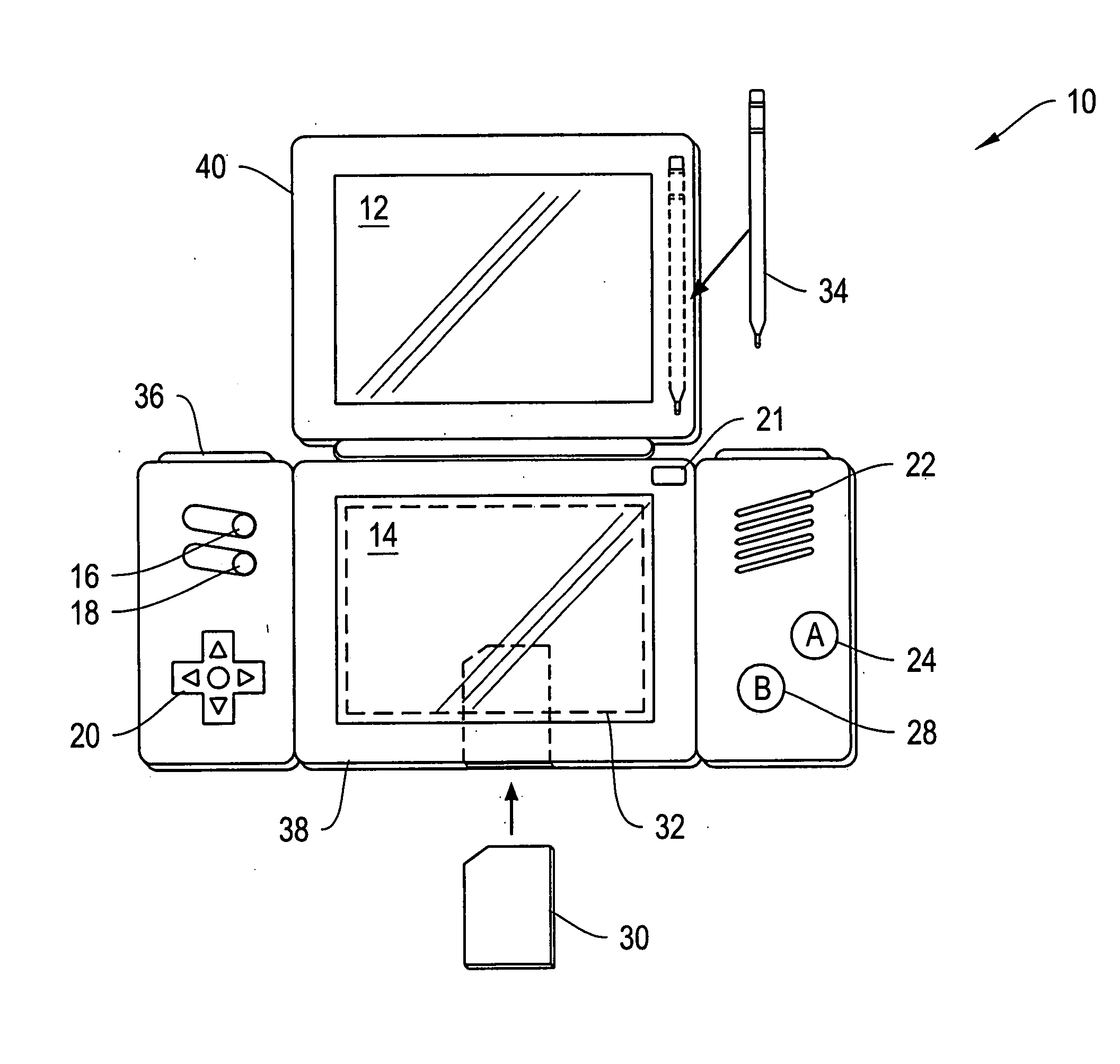
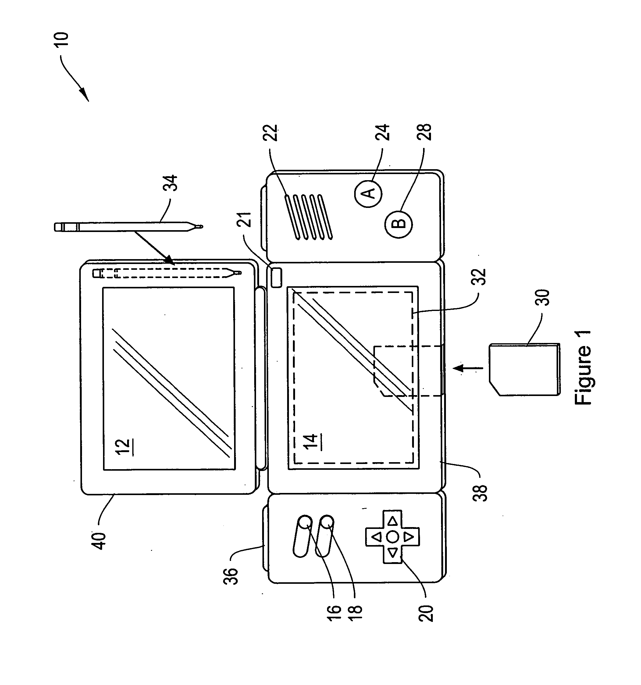
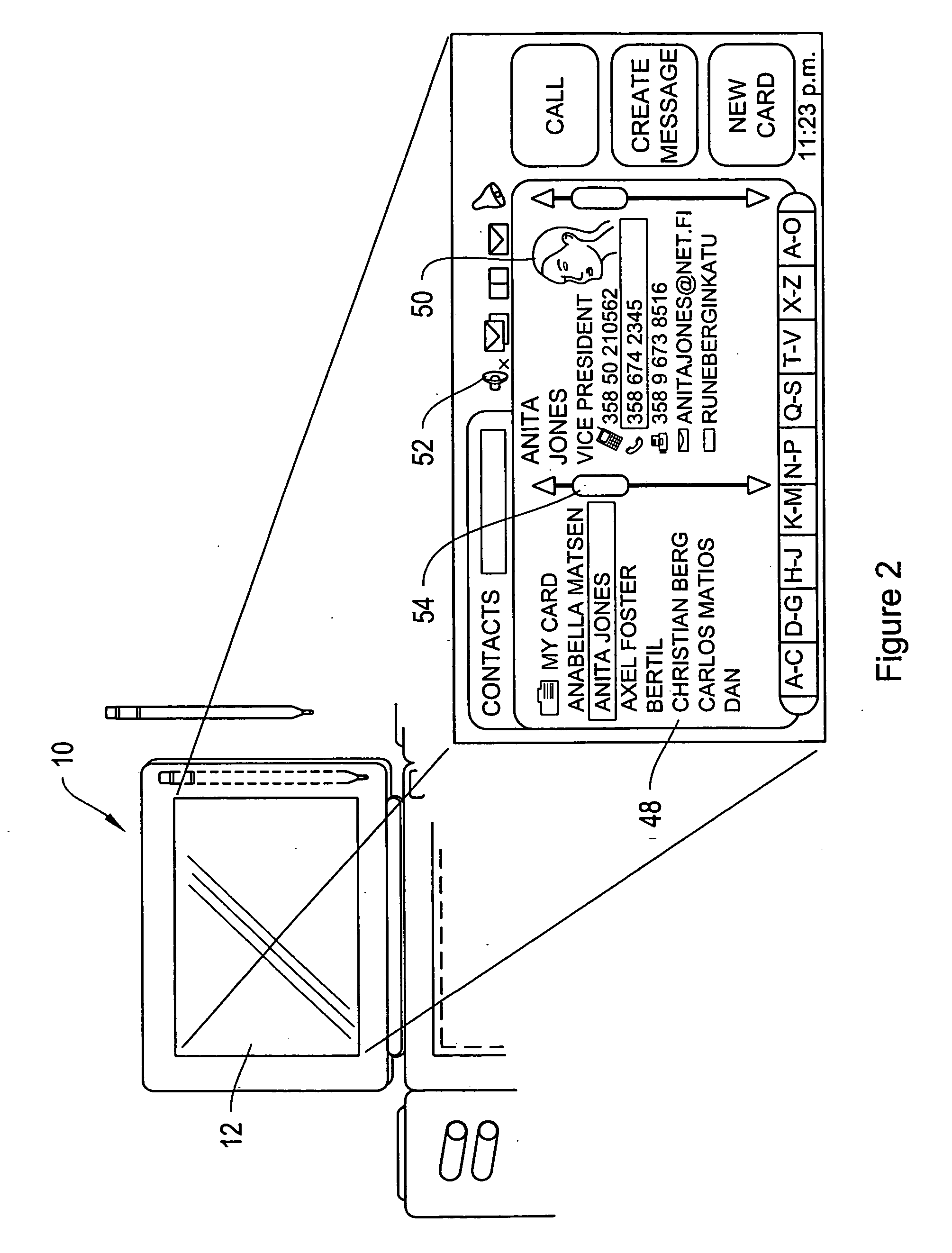
[0039] More particularly, the systems and methods described herein include, among other things portable handheld devices and methods for making portable handheld devices that include low power and brightly lit display panels with sufficient resolution to provide a visual user interface with visually distinct images capable of being viewed under multiple ambient lighting conditions. More particularly, the systems and methods desc...
PUM
 Abstract
Description
Claims
Application Information