Liquid ejection head and method of manufacturing liquid ejection head

Inactive Publication Date: 2006-09-21
FUJIFILM CORP
View PDF4 Cites 27 Cited by
  • Summary
  • Abstract
  • Description
  • Claims
  • Application Information

AI Technical Summary

Benefits of technology

[0026] According to this aspect of the present invention, it is possible to readily manufacture a liquid ejection head that can achieve electrical connections with the piezoelectric elements and the insulation from the liquid chamber, and improve the sealing properties of the piezoelectric elements, without obstructing the driving of the piezoelectric elements.
[0027] As described above, accordin

Problems solved by technology

However, in such a head described in Japanese Patent Application Publication No. 9-314833, since the wires from the piezoelectric elements are extended horizontally and connected to the TFTs, wiring of high-density for the arrangement of the piezoelectric elements corresponding to 1000 dpi (dots per inch) or more is difficult

Method used


Image

  • Liquid ejection head and method of manufacturing liquid ejection head
  • Liquid ejection head and method of manufacturing liquid ejection head
  • Liquid ejection head and method of manufacturing liquid ejection head

Examples


Example

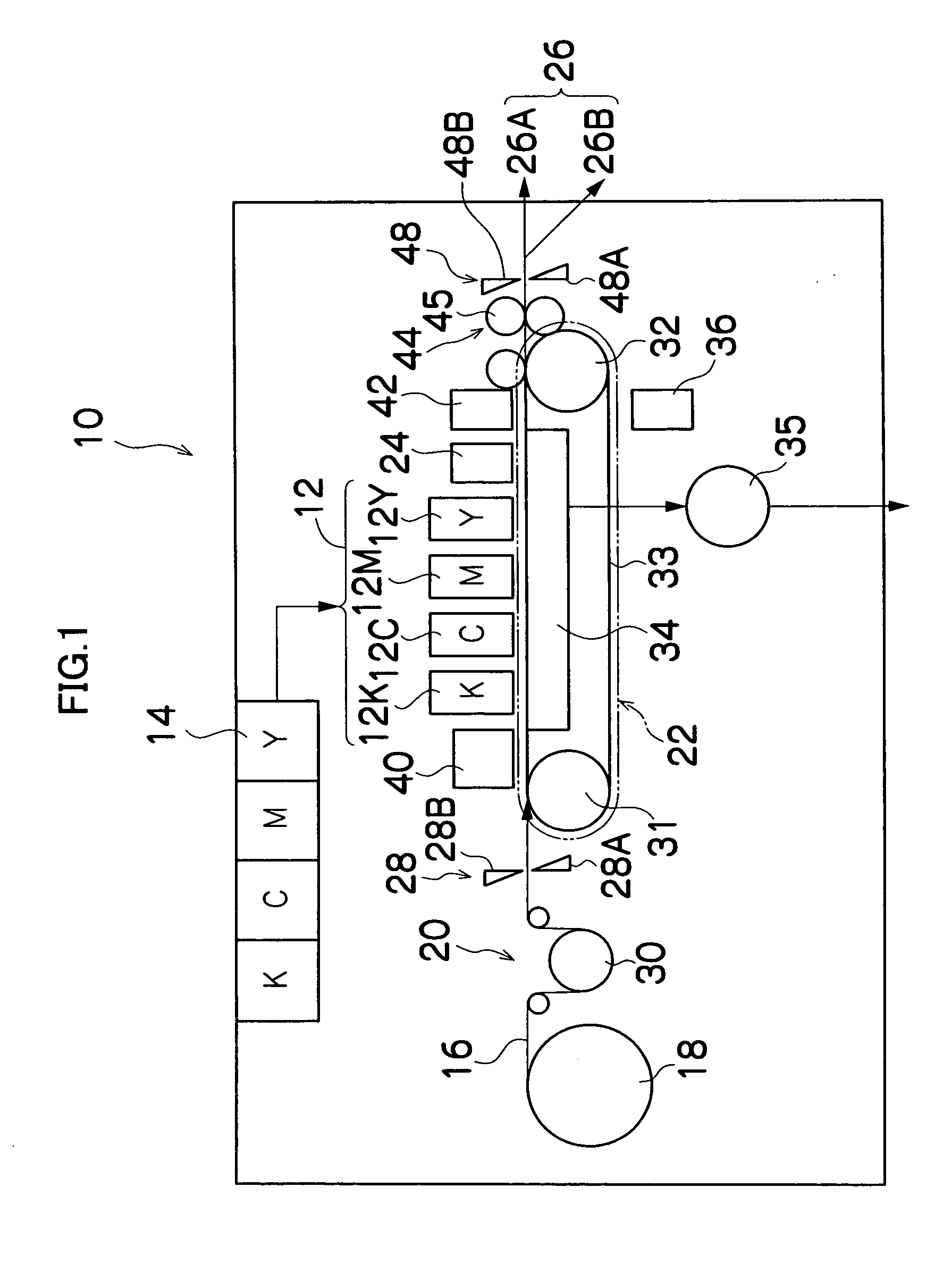
[0051]FIG. 1 is a general schematic drawing showing an approximate view of an inkjet recording apparatus forming an image forming apparatus having a liquid ejection head according to a first embodiment of the present invention.

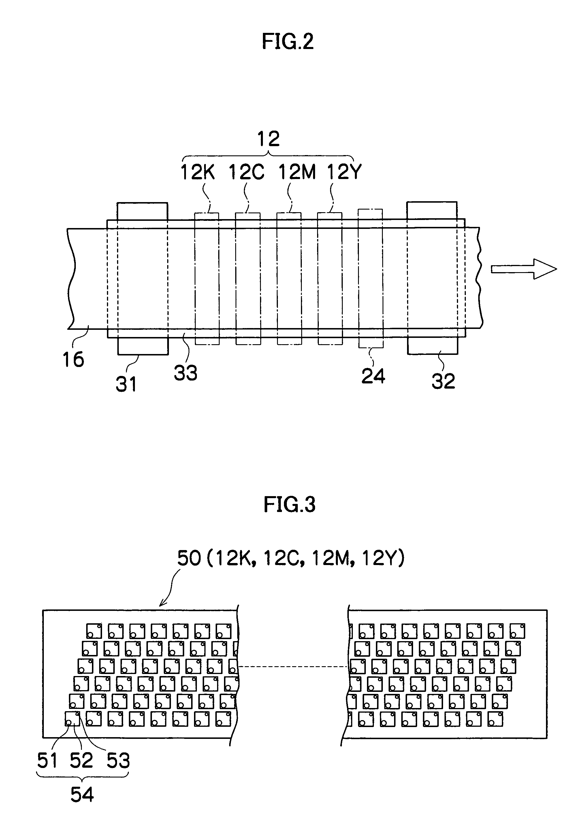
[0052] As shown in FIG. 1, the inkjet recording apparatus 10 comprises: a printing unit 12 having a plurality of print heads (liquid ejection heads) 12K, 12C, 12M, and 12Y for ink colors of black (K), cyan (C), magenta (M), and yellow (Y), respectively; an ink storing and loading unit 14 for storing inks of K, C, M and Y to be supplied to the print heads 12K, 12C, 12M, and 12Y; a paper supply unit 18 for supplying recording paper 16; a decurling unit 20 for removing curl in the recording paper 16; a suction belt conveyance unit 22 disposed facing the nozzle face (ink-droplet ejection face) of the print unit 12, for conveying the recording paper 16 while keeping the recording paper 16 flat; a print determination unit 24 for reading the printed result produced ...

Example

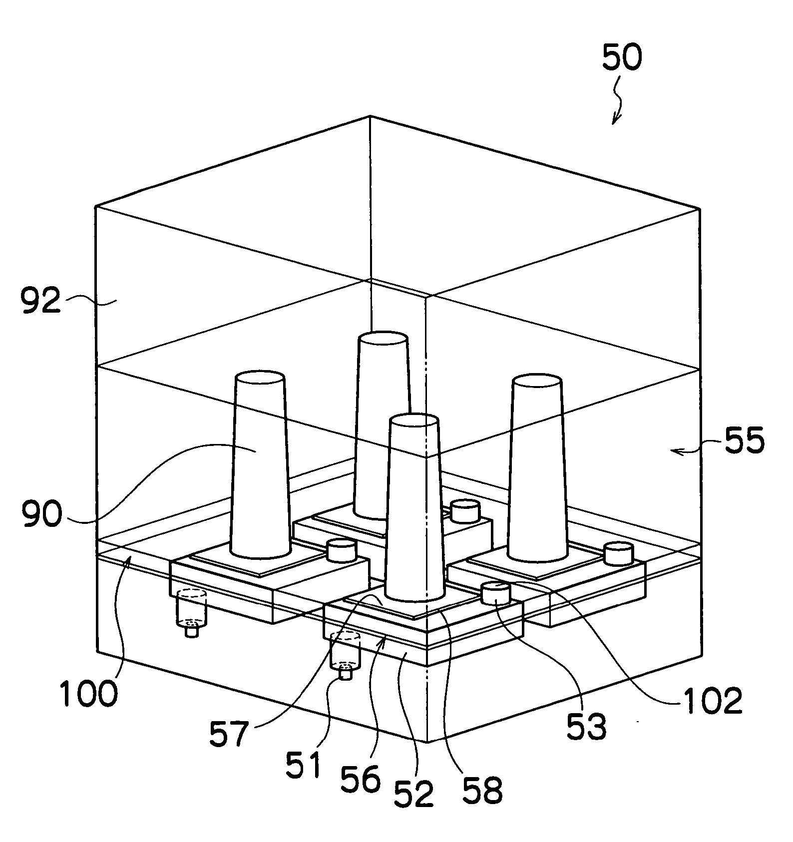
[0144] In the second embodiment, in forming the piezoelectric element cover 100 and the wiring members 90 integrally, the piezoelectric element cover 100 and the wiring members 90 which are resin members are formed by insert molding, onto the diaphragm 56 made of a metal material.

[0145] According to this method, firstly the piezoelectric elements 58 are formed on the diaphragm 56 in positions corresponding to the pressure chambers 52, and then a protective layer (sacrificial layer) is formed by performing the patterning on the periphery of the piezoelectric elements 58 in order to form the cavity sections 104 later in the piezoelectric element cover 100.

[0146]FIGS. 11A and 11B show this situation. FIG. 11A is a plan view perspective diagram showing the periphery of the piezoelectric element 58, and FIG. 11B is a cross-sectional diagram along line 11B-11B in FIG. 11A. In FIG. 11A, the pressure chamber 52, the nozzle 51 and the ink supply port 53 are depicted for the purpose of desc...

Example

[0158] Next, a third embodiment of the present invention is described below. In the first and second embodiments described above, the piezoelectric element cover 100 is formed by a single plate over the whole surface of the print head 50 and has the individual cavity sections 104 (piezoelectric element covers in the narrow sense) corresponding to the piezoelectric elements 58. In the third embodiment, one cavity section is made so as to correspond to a plurality of the piezoelectric elements 58 aligned in one row, so that the plurality of the piezoelectric elements are covered with the one cavity section.

[0159]FIG. 15 shows an oblique view of the piezoelectric element cover according to the third embodiment.

[0160] As shown in FIG. 15, the piezoelectric element cover 100 according to the present embodiment has the cavity section 104 that covers two or more piezoelectric elements 58 arranged in the same one row, rather than having individual cavity sections to separately cover the p...


PUM


Abstract

The liquid ejection head comprises: a plurality of pressure chambers which contain liquid and are arranged in a two-dimensional matrix configuration; a plurality of nozzles which connect to the pressure chambers and eject the liquid; a diaphragm which forms one face of the pressure chambers; a plurality of piezoelectric elements which are formed on a face of the diaphragm reverse to a face thereof adjacent to the pressure chambers, each of the piezoelectric elements corresponding to each of the pressure chambers; a plurality of electrical wires which connect to the piezoelectric elements and extend in a direction substantially perpendicular to the face on which the piezoelectric elements are formed; a sealing member which seals off at least one of the piezoelectric elements and at least one of the electrical wires so that space is formed over a side of the at least one of the piezoelectric elements reverse to a side adjacent to the diaphragm; and a common liquid chamber which supplies the liquid to the pressure chambers and is arranged on a side of the sealing member reverse to a side thereof on which the pressure chambers are arranged.

Description

BACKGROUND OF THE INVENTION [0001] 1. Field of the Invention [0002] The present invention relates to a liquid ejection head and a method of manufacturing a liquid ejection head, and more particularly, to technology for achieving high-density arrangement of electrical wires which supply drive signals to actuators that cause liquid to be ejected from ejection ports of a liquid ejection head. [0003] 2. Description of the Related Art [0004] As an image forming apparatus, an inkjet printer (inkjet recording apparatus) is known, which comprises an inkjet head (liquid ejection head) having an arrangement of a plurality of nozzles (ejection ports) for ejecting ink (liquid). The inkjet printer can form an image on a recording medium by ejecting ink from the nozzles toward the recording medium while the inkjet head and the recording medium are caused to be relatively moved to each other. [0005] For example, as an ink ejection method used in such an inkjet recording apparatus, a piezoelectric ...

Claims


Application Information

Patent Timeline
IPC IPC(8): B41J2/175
CPCB41J2/161B41J2/1637B41J2002/14459B41J2002/14491B41J2202/18B41J2202/20B41J2002/14241
Inventor KOJIMA, TOSHIYA
Owner FUJIFILM CORP
Why Eureka
Try Eureka