This helps you quickly interpret patents by identifying the three key elements:
Problems solved by technology
Method used
Benefits of technology
Benefits of technology
[0017] Therefore, dual-sealing structure in which slight leakage due to failure of scraping at the first sealing part is sealed by the second sealing part is realized, and thus it can be used at the working pressure of 0-2 MPa, and moreover, it is prevented from breaking even when being subjected to the pressure of the high-pressure fuel at 5 MPa or higher.
[0031] Accordingly, the sealing property of the device can further be improved.
Problems solved by technology
However, in the sealing device in the related art shown in FIG. 9, in order to prevent fuel leakage due to excessive abrasion of the seal lip, damage of the rubber-like resilient body, and so on, which may be caused by increase in the pressure of the high-pressure fuel, it has been necessary to construct the pump in such a manner that the pressure of the high-pressure fuel relating to the sealing device is limited normally to 0 to 0.6 MPa.
Therefore, the rubber-like resilient body is thin and when it is subjected to the pressure of the high-pressure fuel of 1 MPa or higher, it may be broken abruptly upon operation.
Since the used fuel has no lubricity, the more the pressure of the high-pressure fuel increases, the more the seal lip is abraded in an abnormal manner, and thus fuel leakage is more likely to occur.
In the case of fuel containing alcohol, the rubber-like resilient body is swelled, and thus is lowered in hardness and strength, whereby abrupt breakage upon operation, or fuel leakage due to decrease of tightening margin of the seal lip may occur.
In addition, since the device is bulky, space saving could not be achieved.
However, since elimination of the drain port may increase the pressure of the high-pressure fuel, it cannot be eliminated for limiting the working pressure of the high-pressure fuel to 0-0.6 MPa, and hence simplification of the pump construction cannot be achieved.
Method used
Image
Click on the blue label to locate the original text in one second.
Reading with bidirectional positioning of images and text.
Examples
first embodiment
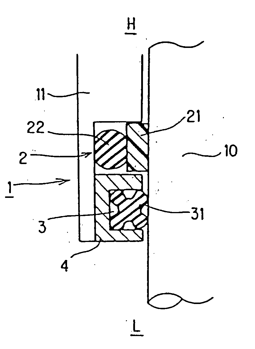
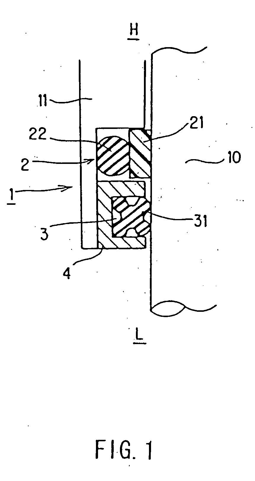
[0042]FIG. 1 shows a sealing device 1 according to a first embodiment, and FIG. 2 shows a peripheralsystem to which the sealing device 1 in FIG. 1 is applied.
[0043] The sealing device 1 in FIG. 1 is used as a sealing device for reciprocating movement, which requires a high sealing property, to be used in a high-pressure fuel pump for pressurizing fuel to a high pressure in an engine of in-cylinder direct injection system that high-pressure fuel is directly injected in a cylinder for combustion, and is employed for seal the high-pressure fuel supplied on the high-pressure side H, which is to be sealed with respect to a axially reciprocating shaft 10.
[0044] In FIG. 1, the sealing device 1 is attached at the end of a housing 11 for sealing a high-pressure fuel (gasoline, light oil, and so on), which is to be sealed, supplied from the high-pressure side H from passing a sliding portion of a shaft guiding portion of the housing 11. Besides, on the low-pressure side L of the sealing de...
second embodiment
[0063]FIG. 4 is a half cross-sectional view showing the sealing device 1 according to the second embodiment. Incidentally, since the configuration, material and the like of each member are the same as those in the first embodiment, description will be omitted.
[0064] In the sealing device 1 shown in FIG. 4, the second sealing part 3 includes a second resin ring 32 that comes into slidable sealing contact with the shaft 10 which is similar to the first sealing part 2, and a second O-ring 33 for urging the second resin ring 32 toward the shaft 10.
[0065] In this arrangement as well, the same effects as the first embodiment is achieved. Moreover, with the second sealing part 3 of this construction, durability against the high-pressure increases and thus usage of the device under higher pressure is realized.
third embodiment
[0066]FIG. 5 is a half cross section showing the sealing device 1 according to the third embodiment. Incidentally, since the configuration, material, and the like are the same as those in the first embodiment other than that the seal retainer 4 is not used, description will be omitted.
[0067] In the sealing device 1 shown in FIG. 5, a U-packing 34 is used as a packing having a back-pressure leaking capability for the second sealing part 3. The packing having the back-pressure leaking capability used for the second sealing part 3 is not limited to the U-packing 34, and other types of packing may be used. Material to be used for this packing is fluorinated rubber or acrylic rubber, which are superior in fuel resistance and heat resistance. Preferably, fluorinated rubber is used.
[0068] In the construction described above as well, the same effects as in the first embodiment are achieved. Also, even when the pressure is accumulated between the first sealing part 2 and the second sealing...
PUM
Abstract
A high performance sealing device having an excellent pressure resistance and realizing a prevention of damage. The sealing device usable at a working pressure of 0 to 2 MPa, and not damaged even if the pressure of high-pressure fuel of 5 MPa or higher is applied thereto, wherein high pressure fuel on the high pressure side H is sealed by a first seal part 2, oil from a cam side on a low pressure side L is sealed by a second seal part 3, and the fuel slightly leaked due to failure of scraping at the first seal part is sealed by the second seal part to form a dual seal structure, and a resin ring 21 coming into slidable sealing contact with a shaft 10 is used in the first seal part 2, whereby abnormal abrasion does not occur even when fuel having less lubricity is used, and the durability of the seal is increased.
Description
[0001] This is a divisional application of application Ser. No. 10 / 479,417, filed Apr. 13, 2004.TECHNICAL FIELD [0002] The present invention relates to a sealing device to be used, for example, as seal for reciprocating movement for a high-pressure fuel pump for pressurizing fuel to a high-pressure. BACKGROUND ART [0003] In recent years, in diesel engines or in gasoline engines, those of in-cylinder direct injection system in which fuel at high pressure is directly injected in a cylinder for combustion have been developed for improved performance such as fuel-efficient, high output, and so on. [0004] In such an engine of in-cylinder direct injection system requires a high-pressure fuel pump for pressurizing fuel to a high pressure, and such high-pressure fuel pump is provided with a sealing device for reciprocating movement in which high sealing property is required. [0005] One of sealing devices for reciprocating movement in the related art is shown in FIG. 9. A sealing device 101 ...
Claims
Application Information
Patent Timeline
Application Date:The date an application was filed.
Publication Date:The date a patent or application was officially published.
First Publication Date:The earliest publication date of a patent with the same application number.
Issue Date:Publication date of the patent grant document.
PCT Entry Date:The Entry date of PCT National Phase.
Estimated Expiry Date:The statutory expiry date of a patent right according to the Patent Law, and it is the longest term of protection that the patent right can achieve without the termination of the patent right due to other reasons(Term extension factor has been taken into account ).
Invalid Date:Actual expiry date is based on effective date or publication date of legal transaction data of invalid patent.

