

System and method for allocating and indicating ranging region in a broadband wireless access communication system
- Summary
- Abstract
- Description
- Claims
- Application Information
AI Technical Summary
Benefits of technology
Problems solved by technology
Method used
Image

Examples
first embodiment
[0064] The MSS performs a ranging operation even when the BS transmits a UL_MAP message not including the UL_MAP IE with UIUC=12 and the MSS receives the UL_MAP message. Therefore, the present invention changes a format of a Downlink Frame Prefix (DLFP) of a downlink frame so that the MSS can perform the ranging operation even when the BS transmits a UL_MAP message not including the UL_MAP IE with UIUC=12.
[0065] Downlink Frame Prefix (DLFP)
[0066] The DLFP is transmitted through a Frame Control Header (FCH) region. A format of the DLFP proposed in the present invention is shown in Table 6 below.
TABLE 6SyntaxSizeNotesDL_Frame_Prefix_Format ( ) {Used subchannel bitmap6 bitsBit #0: Subchannels0-11 are usedBit #1: Subchannels12-19 are usedBit #2: Subchannels20-31 are usedBit #3: Subchannels32-39 are usedBit #4: Subchannels40-51 are usedBit #5: Subchannels52-59 are usedRepetition_Coding_Indication2 bits00 - No repetitioncoding on DL_MAP01 - repetition codingof 2 used on DL_MAP10 - rep...
second embodiment
[0142] The second embodiment provides a scheme in which an MSS can perform ranging through a ranging region previously allocated in an uplink frame, even without including a UL_MAP IE with UIUC=12 in the UL_MAP message.
[0143] Downlink Frame Prefix (DLFP)
[0144] The DLFP is transmitted through a FCH region as described with reference to Table 1. A format of the DLFP information of the second embodiment of the present invention is shown in Table 7 below.
TABLE 7SyntaxSizeNotesDL_Frame_Prefix_Format ( ) {Used subchannel bitmap6 bitsBit #0: Subchannels0-11 are usedBit #1: Subchannels12-19 are usedBit #2: Subchannels20-31 are usedBit #3: Subchannels32-39 are usedBit #4: Subchannels40-51 are usedBit #5: Subchannels52-59 are usedRanging_Change_Indication1 bitInitial Ranging_Change_Indication1 bitRepetition_Coding_Indication2 bits00 - No repetition codingon DL_MAP01 - repetition codingof 2 used on DL_MAP10 - repetition codingof 4 used on DL_MAP11 - repetition codingof 6 used on DL_MAPCodi...
third embodiment
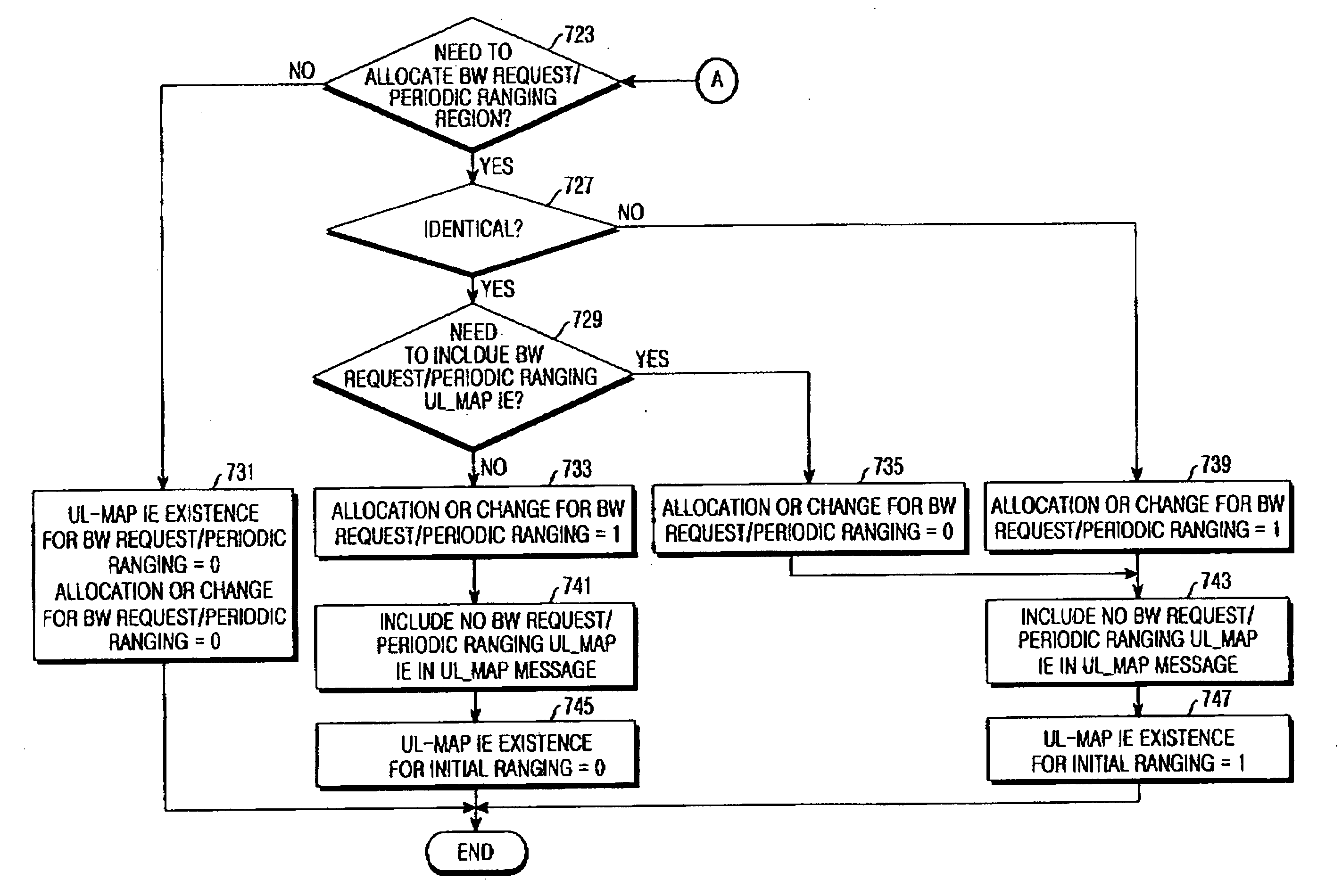
[0155] A DLFP format of the third embodiment of the present invention is the same as the conventional DLFP format shown in Table 1. However, while the Ranging_Change_Indication field in the DLFP format shown in Table 1 indicates a change in allocation of a BW request / periodic ranging region, the Ranging_Change_Indication field in the DLFP format proposed in the third embodiment indicates a change in allocation of the BW request / periodic ranging region or a change in allocation of an initial ranging region as well.
[0156] That is, if a bit value of the Ranging_Change_Indication field is ‘0’ in the conventional DLFP format of Table 1, it means that the BW request / periodic ranging region of the previous frame is identical to the BW request / periodic ranging region of the current frame. In addition, if a bit value of the Ranging_Change_Indication field is ‘1’ in the conventional DLFP format of Table 1, it means that the BW request / periodic ranging region of the previous frame is differen...
PUM
 Abstract
Description
Claims
Application Information