
Circuit and method for detecting ac voltage pulses

a technology of ac voltage pulse and circuit, which is applied in the field of circuit for detecting ac voltage pulse, can solve the problems of requiring a relatively large number of discrete components for outputting and bandpass filtering charge unit signals, impede the miniaturization of subscriber terminals, and high cost of discrete components, so as to reduce the signal rate and low processing frequency , the effect of cost saving

Inactive Publication Date: 2006-09-21
INTEL CORP
View PDF16 Cites 3 Cited by
  • Summary
  • Abstract
  • Description
  • Claims
  • Application Information

AI Technical Summary

Benefits of technology

[0007] In particular, it is an object of the invention to further reduce the number of discrete components required to detect AC voltage pulses at a defined frequency.
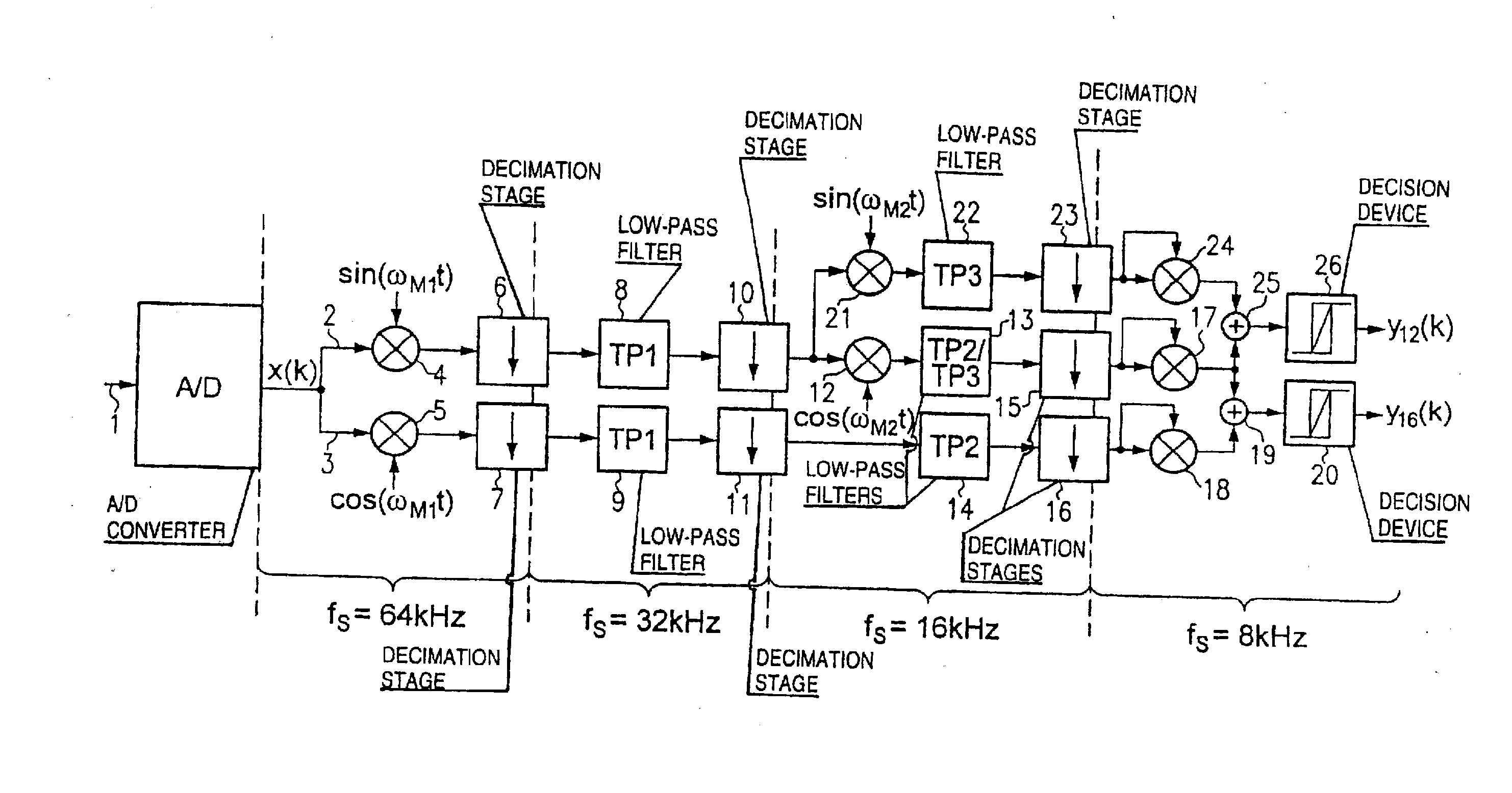
[0043] The inventive method allows completely digital selective identification of various types of AC voltage pulses. In the method, the input signal is down-mixed to low frequencies by being multiplied by different mixing frequency signals. First, this has the advantage that the signal can be filtered considerably more easily in the low-frequency intermediate frequency band than in the original input signal frequency band. A further advantage is that it is possible to use considerably lower signal rates once the input signal has been transformed to the low-frequency band. This means that less powerful signal processors can be used and that the power consumption of the circuit is reduced.

Problems solved by technology

This solution has the disadvantage of requiring a relatively large number of discrete components for outputting and bandpass filtering the charge unit signals.
Discrete components are expensive and impede further miniaturization of the subscriber terminals.

Method used


Image

  • Circuit and method for detecting ac voltage pulses
  • Circuit and method for detecting ac voltage pulses
  • Circuit and method for detecting ac voltage pulses

Examples


Embodiment Construction

[0048] Referring now to the sole drawing FIG. 1, there is shown a detection circuit for detecting AC voltage pulses at a defined frequency. This detection circuit is particularly suitable for detecting the charge unit signals that are transmitted via the telephone network. The circuit and the detection principle are not, however, restricted to this application, but can be used wherever identification pulses at a defined frequency should be selectively detected.

[0049] The analog input signal 1 is first of all supplied to the analog / digital converter A / D and is converted to a sequence of digital sample values x(k). If the circuit in a telephone is used for detecting the charge unit pulses, then the charge unit signals are digitized by the same analog / digital converter that is also used to convert the speech signal to digital values, because the charge unit pulses are not output from the speech path in this inventive solution.

[0050] The digitized sample values x(k) are now supplied t...


PUM


Abstract

A detection circuit and method for detecting AC voltage pulses at a defined frequency relate to first transforming an input signal to a low-frequency signal by multiplying the input signal by a mixing frequency. This down-mixed signal can then be filtered and evaluated. The circuit is particularly suitable for identifying charge unit signals in the telephone network.

Description

PRIORITY INFORMATION [0001] This application is a Continuation of U.S. Application Ser. No. 10 / 431,901, filed May 8, 2003, now published as U.S. Patent Application Publication No. 2003 / 0207677 A1 on Nov. 6, 2003, which application and publication are incorporated herein by reference.BACKGROUND Field of the Invention [0002] The invention relates to a circuit for detecting AC voltage pulses at a defined frequency, to a telephone having such a circuit, and to a method for identifying AC voltage pulses at a defined frequency. [0003] In the European analog telephone network, charge unit pulses are transmitted to the subscriber terminals, in order to allow the accumulating charges to be detected at the subscriber end. The charge unit pulses are short AC voltage pulses at a frequency of 16 kHz, or in some countries at about 12 kHz. These charge pulses must be identified and counted in the subscriber device. [0004] Originally, the charge unit signals were output from the reception path by a...

Claims


Application Information

Patent Timeline
Patent Type & Authority Applications(United States)
IPC IPC(8): H04M1/00H04L27/14H04M15/00
CPCH04L27/14
Inventor HAUSER, THOMASHURTGEN, FRANKKRANZ, CHRISTIAN
Owner INTEL CORP
Learn More