Sample rate converter for reducing the sampling frequency of a signal by a fractional number

Active Publication Date: 2006-05-18
MEDIATEK INC
View PDF9 Cites 32 Cited by
  • Summary
  • Abstract
  • Description
  • Claims
  • Application Information

AI Technical Summary

Benefits of technology

[0009] A sample rate converter reduces the sampling rate of a signal by a fractional number U / D, where U represents an up-sampling rate and D represents a down-sampling rate. The converter comprises an input for receiving an input data stream at a first rate and an FIR filtering stage. The FIR filtering stage comprises a set of D polyphase filter branches, each branch including a set of filter coefficients which operate on a sample of the input signal. The converter also comprises a commutative switch which selectively connects a sample of the input data stream to one of the polyphase filter branches, the switch being arranged to skip every U-1 filter branches during a cycle through the filter branches. An output outputs an output data stream at a second data rate which is lower than the first data rate.
[0010] The sample rate converter has an advantage of removing the need to up-sample the input data stream. This removes the need to perform calculations on samples which will only be discarded. This reduces the amount of computation required in the filter. This also avoids the need to operate at a high frequency which may not be readily available on an integrated circuit. The sample rate converter can also have the advantage of reducing the overall number of filtering stages used, compared with conventional sample rate converters, as the FIR filtering stage can offer a high degree of anti-aliasing filtering. Preferably, the FIR filtering stage has a SINC3 response. This will have nulls at frequencies equal to multiples of Fout, ensuring the best possible attenuation of aliases using this kind of function. Applying a high level of filtering within the sample rate converter can allow the removal of a previously needed SINC4 filter (see SINC4 filter 44 in FIG. 5). This allows reductions in die area and power consumption.
[0011] Preferably, the filter coefficients are calculated on demand. This provides flexibility in changing the sampling rate of a digital signal and reduces the amount of storage required for filter coefficients. Any fractional conversion rate can be achieved by choosing the values of U and D. A specific filter coefficient is determined by the index position of this coefficient inside the FIR filter (this depends on the up-sampling rate U) and the formula that takes this index and calculates the coefficient (this depends on the down-sampling rate D).
[0012] Preferably, each polyphase filter branch comprises N coefficient multiplication stages where a coefficient is multiplied by an input sample. The converter comprises N multiplier and accumulation units, with each multiplier and accumulation unit being arranged to perform a coefficient multiplication stage of a plurality of filter branches and to the accumulate the results. This can be achieved by rearranging the elements of the filtering stage and has the advantage of reducing the amount of hardware required to perform the filtering. In this way, a small number of multiplier and accumulation units is reused to perform the required multiplication stages of the filter branches. Each multiplier and accumulation unit is effectively allocated to a column of the filtering stage. It is possible to move accumulated data values from one multiplier and accumulation unit to another after each switching cycle such that an output sample is always taken from one multiplier and accumulation unit. Alternatively, the coefficients applied to the coefficient multiplication stages can be managed in such a way that each multiplier and accumulation unit can accumulate results over a sequence of N switching cycles and after each switching cycle an output sample is taken from one of the multiplier and accumulation units. On each of the N switching cycles a different one of the N multiplier and accumulation units provides the output sample, on a rotational basis. This has a further advantage of reducing the amount of data movement within the hardware.

Problems solved by technology

However, this solution cannot achieve decimation by a fractional number.
This has a disadvantage that a change in the decimation factor requires a new set of FIR filter coefficients.
One issue with this arrangement is that only a CIC filter 42 with the maximum order of two can be used and therefore another stage of filtering 44 and decimation is required.
Another issue is that it requires an additional sigma-delta modulator.
Both of these issues have a disadvantage of requiring further die space and power to implement.

Method used


Image

  • Sample rate converter for reducing the sampling frequency of a signal by a fractional number
  • Sample rate converter for reducing the sampling frequency of a signal by a fractional number
  • Sample rate converter for reducing the sampling frequency of a signal by a fractional number

Examples


Embodiment Construction

[0035] The present invention will be described with respect to particular embodiments and with reference to certain drawings but the invention is not limited thereto but only by the claims. The drawings described are only schematic and are non-limiting.

[0036] This invention is not limited in its application to the details of construction and the arrangement of components set forth in the following description or illustrated in the drawings. The invention is capable of other embodiments and of being practiced or of being carried out in various ways. Also, the phraseology and terminology used herein is for the purpose of description and should not be regarded as limiting. The use of the terms “including,”“comprising,”“having,”37 containing,” or “involving,” and variations thereof herein, is meant to encompass the items listed thereafter and equivalents thereof as well as additional items.

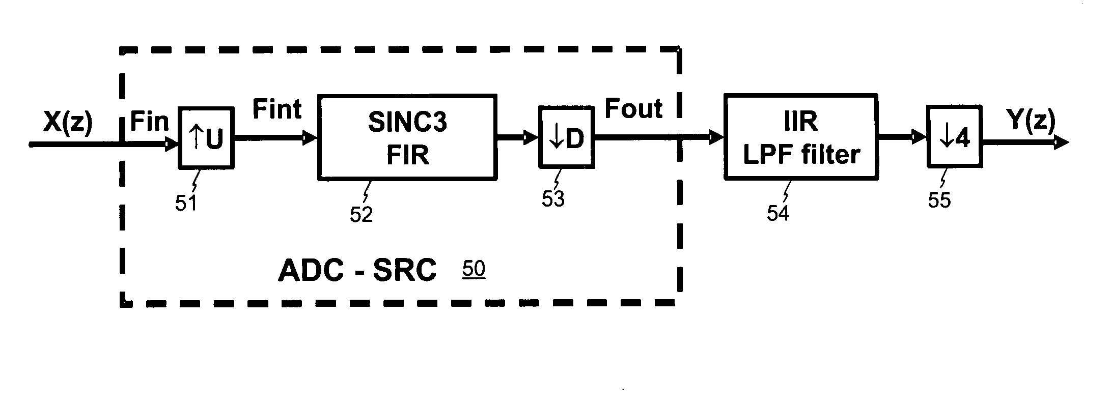
[0037] Referring again to FIG. 6, this schematically shows a sample rate converter (SRC) which f...


PUM


Abstract

A sample rate converter reduces the sampling rate of a signal by a fractional number U / D, where U represents an up-sampling rate and D represents a down-sampling rate. The converter comprises an input for receiving an input data stream at a first rate and an FIR filtering stage. The FIR filtering stage comprises a set of D polyphase filter branches, each branch including a set of filter coefficients which operate on a sample of the input signal. The converter also comprises a commutative switch which selectively connects a sample of the input data stream to one of the polyphase filter branches, the switch being arranged to skip every U-1 filter branches during a cycle through the filter branches. An output outputs an output data stream at a second data rate which is lower than the first data rate.

Description

PRIORITY INFORMATION [0001] This application claims priority from provisional application Ser. No. 60 / 627,648 filed Nov. 12, 2004, which is incorporated herein by reference in its entirety.FIELD OF THE INVENTION [0002] This invention relates to sample rate conversion, which may be required as part of an analog-to-digital converter (ADC) or a Digital Down Converter (DDC). BACKGROUND TO THE INVENTION [0003] Analog-to-digital converters (ADCs) are increasingly being based on an oversampling technique such as a sigma-delta (ΣΔ) architecture. FIG. 1 illustrates a simple architecture as used in a sigma delta analog-to-digital converter (ADC). An analog sigma-delta modulator 11 receives an analog input signal 10 and generates a high rate, low bitwidth, digital signal 12. This signal is then applied to a digital decimation stage 13 which converts the signal to a lower rate, higher bitwidth, digital signal 14. The sigma-delta modulator 11 can be a single bit or a multi-bit modulator. [0004] ...

Claims


Application Information

Patent Timeline
IPC IPC(8): H03M7/00
CPCH03H17/0275H03H17/0685
Inventor ANTONESEI, GABRIEL
Owner MEDIATEK INC
Why Eureka
Try Eureka