
Automatic perspective distortion detection and correction for document imaging

a document imaging and automatic technology, applied in the field of image readers, can solve the problems of affecting the accuracy of image readers, so as to avoid the effect of perspective distortion

Inactive Publication Date: 2006-09-21
PSION TEKLOGIX
View PDF14 Cites 98 Cited by
  • Summary
  • Abstract
  • Description
  • Claims
  • Application Information

AI Technical Summary

Benefits of technology

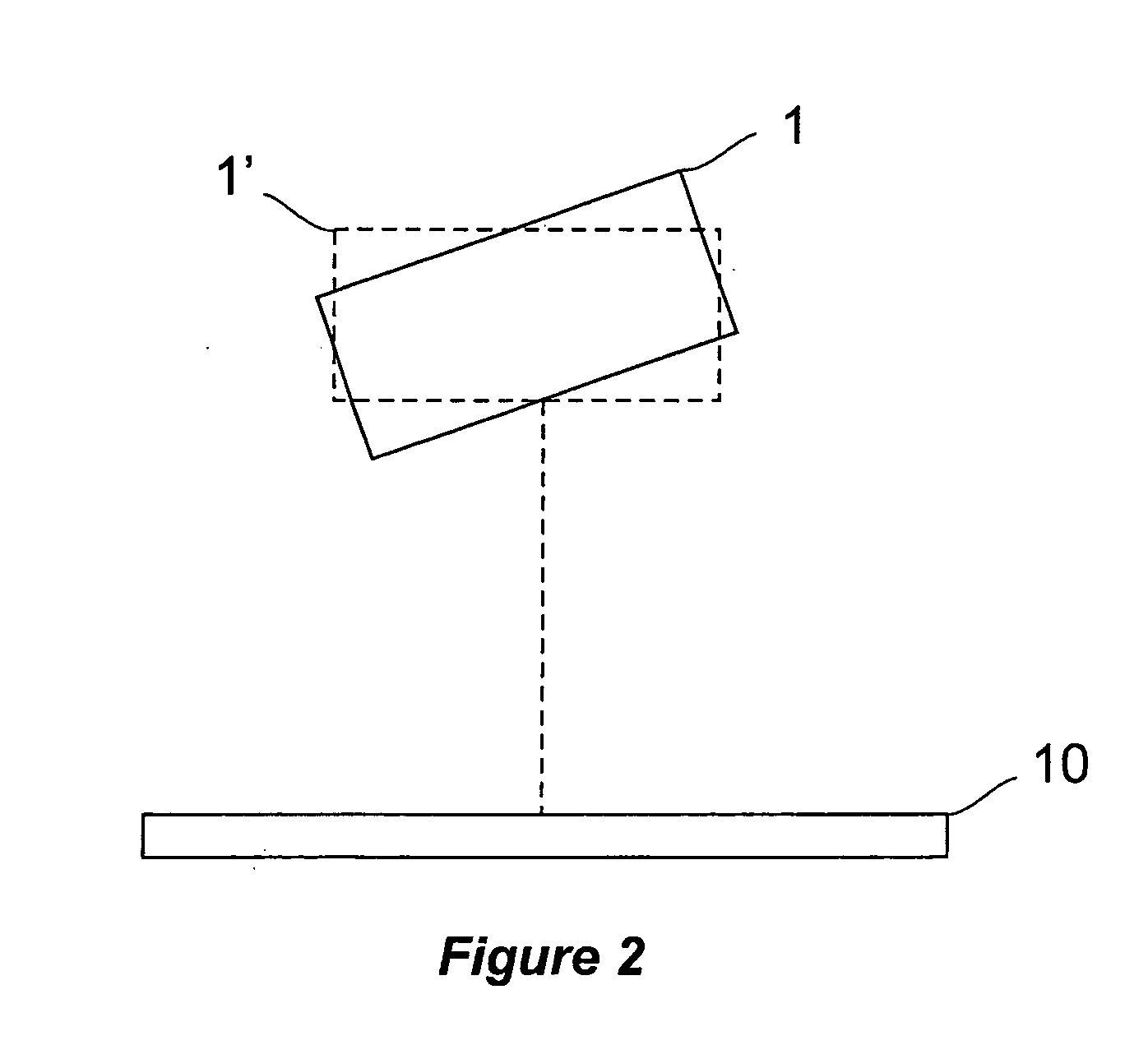
[0009] The present invention is further directed to a method and apparatus for positioning an image reader having a rectangular field of view to avoid perspective distortion in a captured image wherein the captured image has special boundary markers located at the corners of the image having a rectangular shape. The image reader is positioned by capturing an image, calculating the distance between the special boundary markers and the field of view corners and determining if the distances are all the same within a predetermined tolerance. If the distances are not the same the image reader is repositioned by the operator and the image recaptured until the distances are all the same within the predetermined tolerance. Further, the special boundary markers may include a unique identifier marker different from the other special boundary markers, which is used to correct orientation errors in the captured image.

Problems solved by technology

One of the main challenges with portable image readers however is the perspective distortion caused by inconsistent image reading positions.
It is difficult for an operator to know the ideal point from where to capture an image of a target such as a document.
While these methods do not require user input to manually identify the document corners, additional complexity is added to the image reader.
As a result it may be difficult to define the boundaries of the document by statistical methods.
Further, the prior art accounts for correction of perspective distortion, but cannot correct for orientation.

Method used


Image

  • Automatic perspective distortion detection and correction for document imaging
  • Automatic perspective distortion detection and correction for document imaging
  • Automatic perspective distortion detection and correction for document imaging

Examples


Embodiment Construction

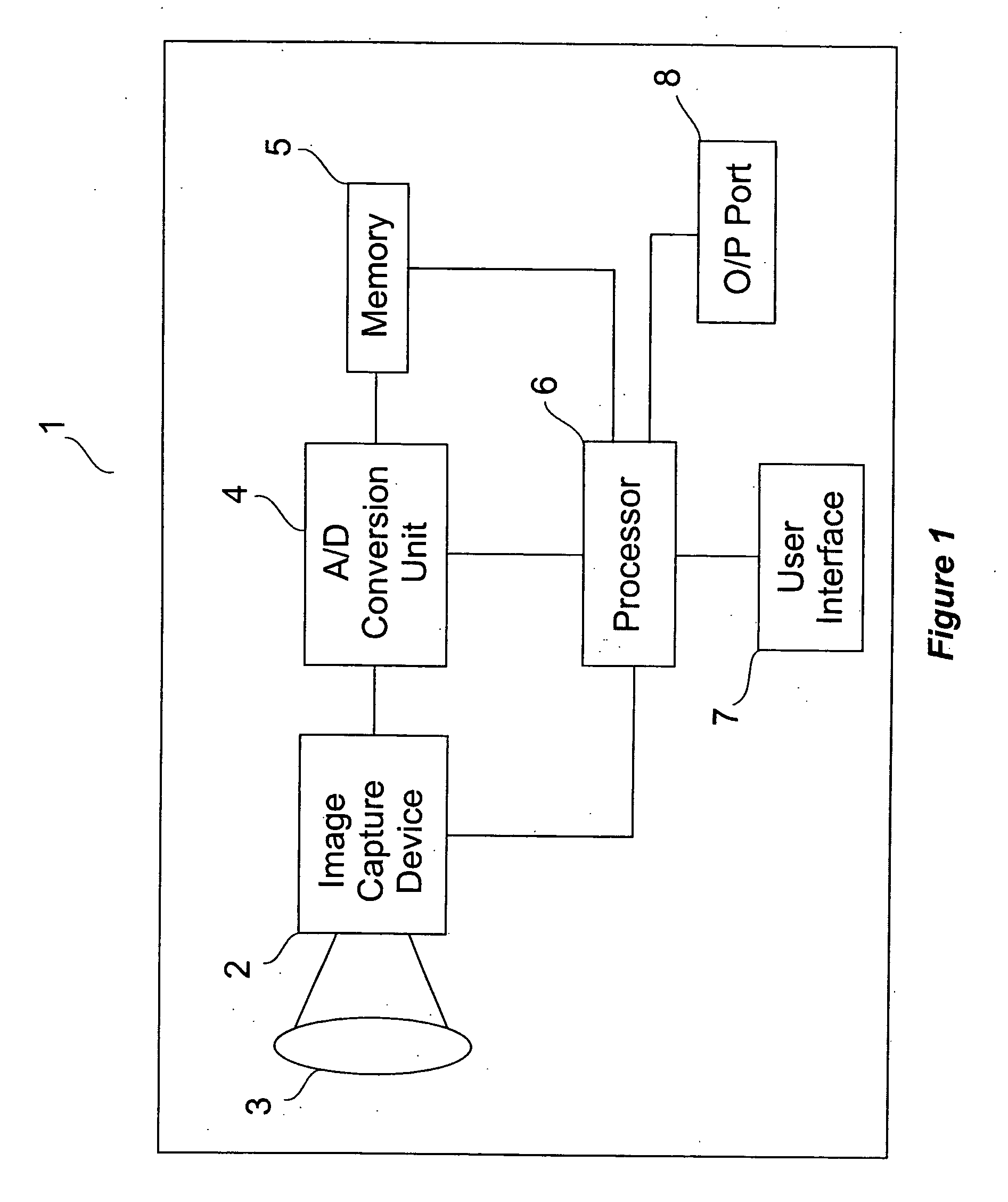
[0024] A conventional image reader, such as a portable image reader 1 is shown in the simplified diagram of FIG. 1. It comprises an image capture device 2, such as a CCD or CMOS image sensor, an optical system 3 mounted over the image sensor, an analog-to-digital A / D) conversion unit 4, memory 5, processor 6, user interface 7 and output port 8.

[0025] The analog information produced by image capture device 2 is converted to digital information by A / D conversion unit 4. A / D conversion unit 4 may convert the analog information received from image capture device 2 in either a serial or parallel manner. The converted digital information may be stored in memory 5 (e.g., random access memory or flash memory). The digital information is then processed by processor 6. Additionally or alternatively, other circuitry (not shown) may be utilized to process the captured image such as an application specific integrated circuit (ASIC). User interface 7 (e.g., a touch screen, keys, and / or the like)...


PUM


Abstract

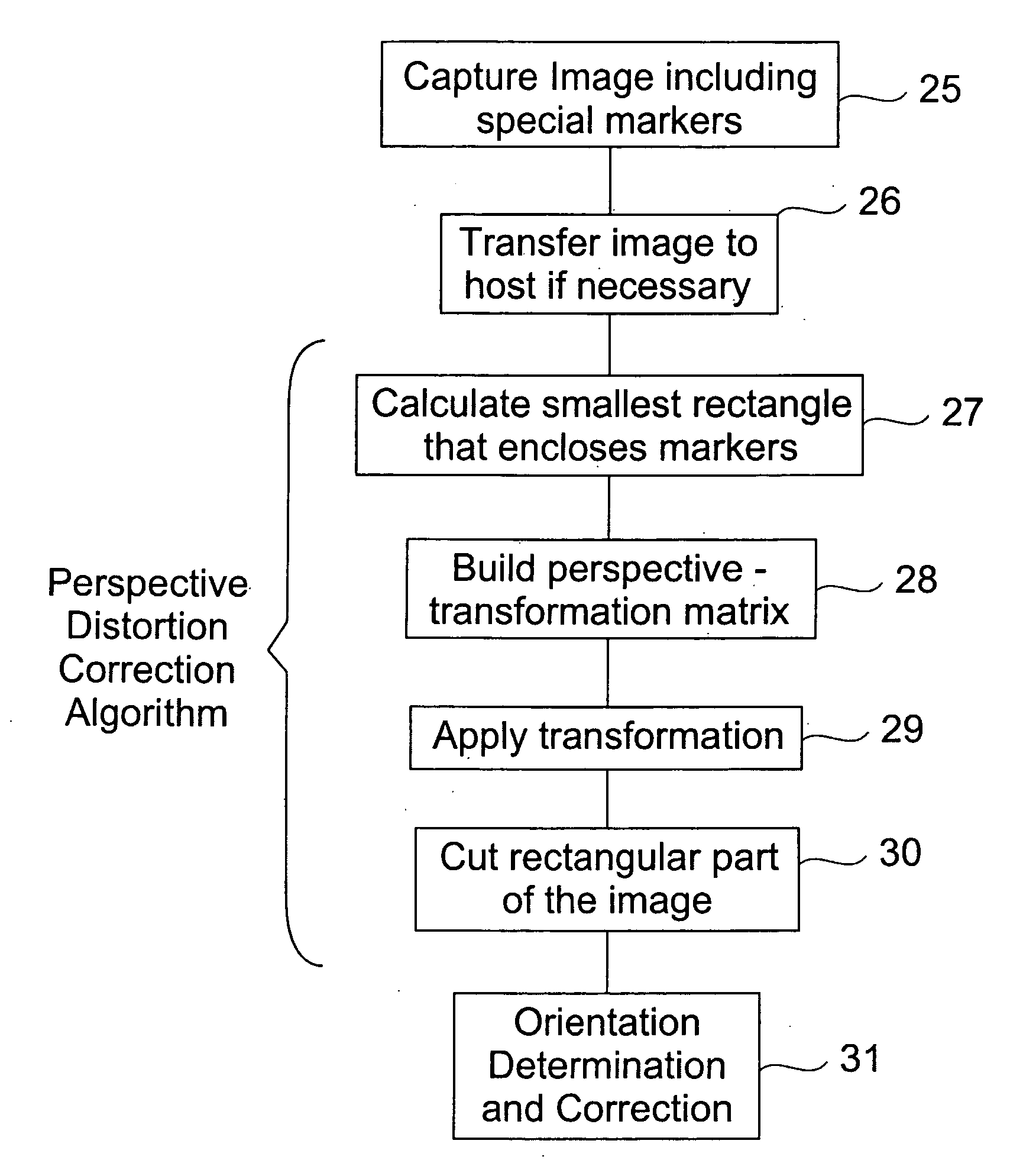
A method and apparatus for detecting and correcting perspective distortion for document imaging is described. The document template of the present invention contains special markers that define the corners of the document. One of these markers, different from the others, uniquely identifies a particular corner. When an image of a document is captured and it is found to contain perspective distortion, the smallest rectangle that encloses the special markers in the captured image is calculated and geometric transforms are used to map the special markers in the captured image to the corners of the smallest rectangle. To correct for orientation errors during image capture, the captured image is rotated based on the location of the unique marker. The present invention can also provide feedback to the operator as the image is being captured. This feedback guides the operator to properly align the image reader for substantially perspective distortion-free imaging.

Description

FIELD OF INVENTION [0001] The present invention relates generally to the field of image readers, and more particularly to a method and apparatus for correcting perspective distortions and orientation errors. BACKGROUND OF THE INVENTION [0002] The use of portable image readers over fixed-mount image readers is increasing and these portable image readers are seeing applications in many industries. One of the main challenges with portable image readers however is the perspective distortion caused by inconsistent image reading positions. With fixed-mount systems, such as a document scanner, the image reader is placed in such a manner that the optical path of the image reader is perpendicular to the image plane. With portable systems, however, the position of the image reader is dependent on a human operator. It is difficult for an operator to know the ideal point from where to capture an image of a target such as a document. More often than not, the user captures the image at an oblique...

Claims


Application Information

Patent Timeline
IPC IPC(8): G06K9/40G06V10/24
CPCG06K9/32G06V10/24
Inventor ORHUN, UFUK
Owner PSION TEKLOGIX
Learn More