Receiver apparatus and method of processing received signal which attain optimum SNR

Active Publication Date: 2006-09-21
FUJITSU SEMICON LTD
View PDF8 Cites 7 Cited by
  • Summary
  • Abstract
  • Description
  • Claims
  • Application Information

AI Technical Summary

Benefits of technology

[0025] According to at least one embodiment of the present invention, the intermediate frequency of the intermediate frequency signal is adjusted in response to at least one of the signal speed and channel frequency interval of the received signal, thereby attaining a desired intermediate frequency, which optimizes the SNR after A / D conversion. In so doing, the intermediate frequency signal is A / D-converted into a digital signal, which is then subjected to digital filtering such that its frequency band is limited to the frequency band of the desired channel. This achieves sufficient frequency selectivity with respect to the desired channel without use of a SAW filter.
[0026] With the optimization of the SNR of the received signal, the designing of a system and a demodulation unit becomes easier when implementing a high-quality information transmission system by use of multi-value transmission. Further, since the need for a SAW filter is eliminated, it is now possible to implement the tuner unit and the demodulation unit as a single chip, which contributes to cost reduction.

Problems solved by technology

Accordingly, how to prevent the degradation of the SNR becomes a main issue when implementing a high-quality information transmission system.
In order to change the sampling frequency, there is a need to provide a special circuit configuration and oscillator for achieving such function, which is not desirable from a cost point of view.
Accordingly, the configuration of the related-art CATV receiver apparatus as shown in FIG. 1 has a problem in that an optimum SNR cannot be attained.

Method used


Image

  • Receiver apparatus and method of processing received signal which attain optimum SNR
  • Receiver apparatus and method of processing received signal which attain optimum SNR
  • Receiver apparatus and method of processing received signal which attain optimum SNR

Examples


Embodiment Construction

[0041] In the following, embodiments of the present invention will be described with reference to the accompanying drawings.

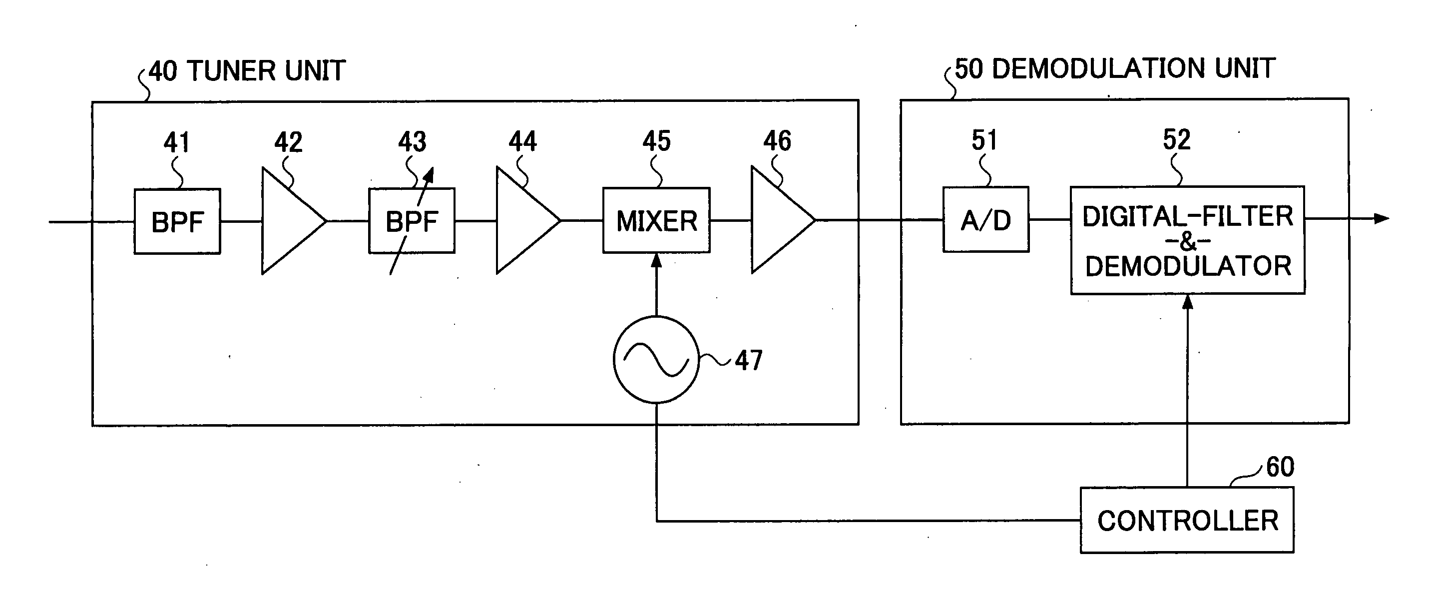
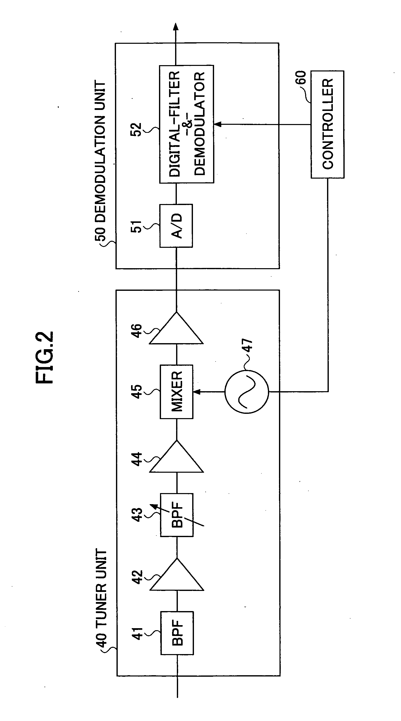
[0042]FIG. 2 is a block diagrams showing an example of the configuration of a CATV receiver apparatus according to the present invention. Although the configuration of FIG. 2 is suitable for use as a CATV receiver apparatus, for example, the present invention is not limited to a CATV system and applicable to receiver apparatus in general.

[0043] The CATV receiver apparatus of FIG. 2 includes a tuner unit 40, a demodulation unit 50, and a controller 60. The tuner unit 40 includes a band-pass filter 41, a first amplifier 42, a band-pass filter 43, a second amplifier 44, a mixer 45, a third amplifier 46, and a VCO 47. The demodulation unit 50 includes an A / D converter 51 and a digital-filter-&-demodulator 52.

[0044] The band-pass filter 41 passes only a range of effective CATV channels among the frequency components of the received signal. Namely, the band-pass f...


PUM


Abstract

A receiver apparatus includes a band-pass filter having a variable frequency band coupled to a node for receiving a received signal including a plurality of channels to output at an output node thereof a limited-band signal made by limiting a frequency band of the received signal to a frequency band of a desired channel, a frequency conversion unit coupled to the output node of the band-pass filter to output at an output node thereof an intermediate frequency signal made by converting frequencies of the limited-band signal, and a control unit configured to adjust an intermediate frequency of the intermediate frequency signal by controlling the frequency conversion unit in response to at least one of a signal speed and a channel frequency interval of the received signal.

Description

CROSS-REFERENCE TO RELATED APPLICATIONS [0001] The present application is based upon and claims the benefit of priority from the prior Japanese Patent Application No. 2005-073982 filed on Mar. 15, 2005, with the Japanese Patent Office, the entire contents of which are incorporated herein by reference. BACKGROUND OF THE INVENTION [0002] 1. Field of the Invention [0003] The present invention generally relates to receiver apparatuses and methods of processing received signals, and particularly relates to a receiver apparatus and method of processing a received signal with respect to a received signal including a plurality of channels. [0004] 2. Description of the Related Art [0005] In recent years, the amount of digital information that is transmitted and received has been increasing in order to provide digital information having higher quality. As a method of transmitting a large amount of information efficiently, a QAM (quadrature amplitude modulation) method that transmits informati...

Claims


Application Information

Patent Timeline
IPC IPC(8): H04B1/26H04B1/16H04L27/38H04N5/44H04N7/10
CPCH04B1/1036
Inventor SUGATA, AKIHIKO
Owner FUJITSU SEMICON LTD
Why Eureka
Try Eureka