Virtual Private Cluster

Active Publication Date: 2006-09-21
III HLDG 12 LLC
View PDF101 Cites 62 Cited by
  • Summary
  • Abstract
  • Description
  • Claims
  • Application Information

AI Technical Summary

Benefits of technology

[0020] The method next comprises establishing partitions of the group of compute resources to fairly distribute available compute resources amongst a plurality of organizations and presenting only partitioned resources accessible by each organization to users within each organization, wherein the resources presented to each

Problems solved by technology

There was previously no mechanism to soft partition a cluster or a group of clusters to provi

Method used


Image

  • Virtual Private Cluster
  • Virtual Private Cluster
  • Virtual Private Cluster

Examples


Embodiment Construction

[0028] Various embodiments of the invention are discussed in detail below. While specific implementations are discussed, it should be understood that this is done for illustration purposes only. A person skilled in the relevant art will recognize that other components and configurations may be used without parting from the spirit and scope of the invention.

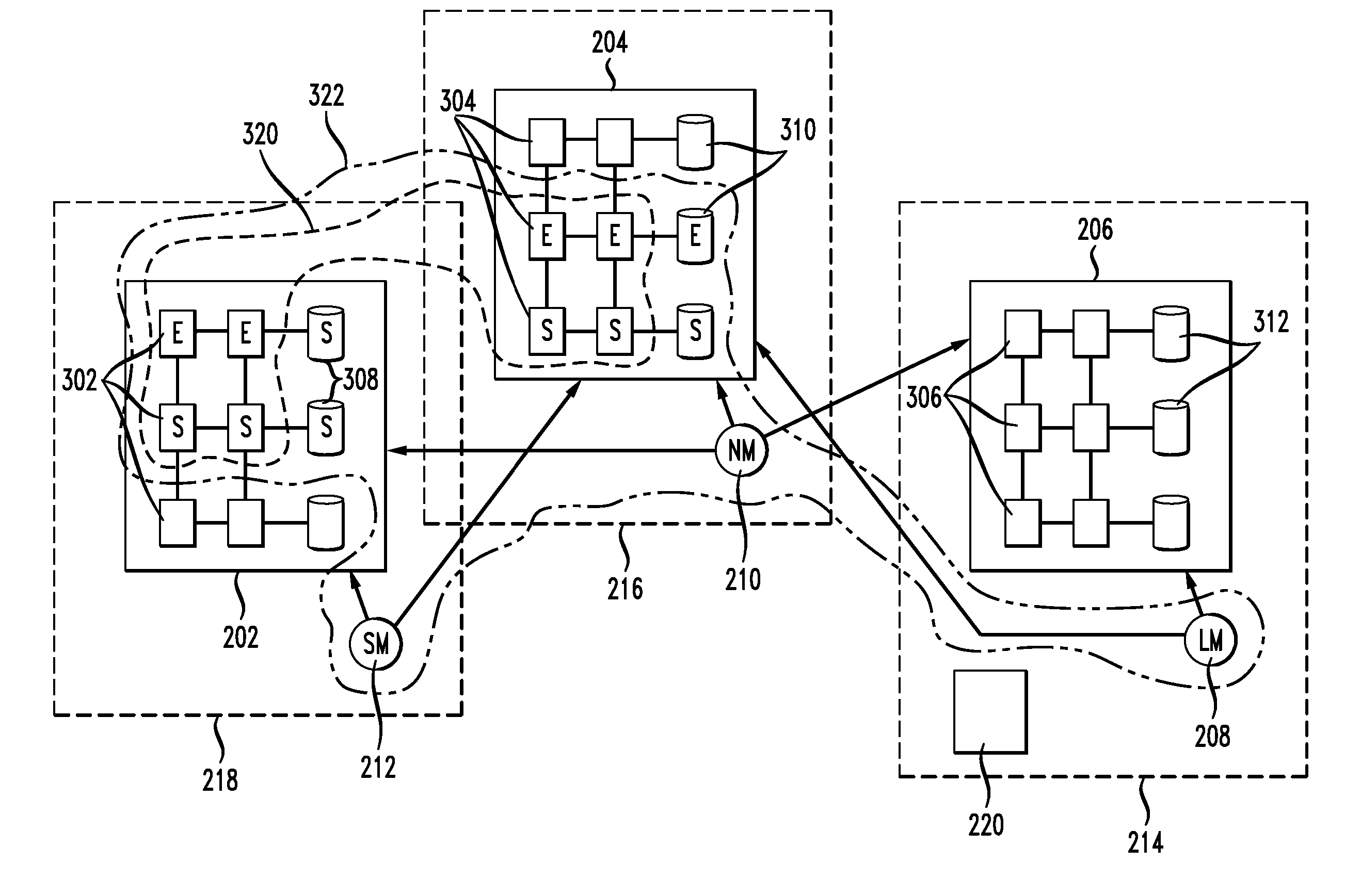
[0029]FIG. 3 illustrates in more detail the example arrangement of three clusters 218, 216 and 214. In this figure, block 218 includes a group of compute nodes 312 and other compute resources 308 organized as a cluster 202. Block 216 includes compute nodes 304 and resources 310 organized as cluster 204. Block 214 includes compute nodes 306 and resources 312 in cluster 206.

[0030] One embodiment of the invention is a method of creating a virtual private cluster. The basic method steps are set forth in FIG. 4 and these will be discussed with further reference to FIG. 3. The method comprises first aggregating compute resources 402. ...


PUM


Abstract

The present invention provides a system, method and computer-readable media for generating virtual private clusters out of a group of compute resources. Typically, the group of compute resources involves a group of clusters independently administered. The method provides for aggregating the group of compute resources, partitioning the aggregated group of compute resources and presenting to each user in an organization a partition representation the organization's virtual private cluster. The users transparently view their cluster and have control over its operation. The partitions may be static or dynamic.

Description

PRIORITY CLAIM [0001] The present application claims priority to U.S. Provisional Application No. 60 / 662,240 filed Mar. 16, 2005, the contents of which are incorporated herein by reference.BACKGROUND OF THE INVENTION [0002] 1. Field of the Invention [0003] The present invention relates to clusters and more specifically a system and method of creating a virtual private cluster. [0004] 2. Introduction [0005] The present invention applies to computer clusters and computer grids. A computer cluster may be defined as a parallel computer that is constructed of commodity components and runs commodity software. FIG. 1 illustrates in a general way an example relationship between clusters and grids. A cluster 110 is made up of a plurality of nodes 108A, 108B, 108C, each containing computer processors, memory that is shared by processors in the node and other peripheral devices such as storage discs connected by a network. A resource manager 106A for the node 110 manages jobs submitted by user...

Claims


Application Information

Patent Timeline
IPC IPC(8): G06F11/00H04L47/80
CPCG06F9/5027G06F9/5061G06F9/5072G06F9/5077G06F11/2038G06Q10/06G06F2209/5014H04L29/08144H04L47/70G08C17/00G06F15/173G06F2209/509H04L67/1002H04L67/1001H04L47/83H04L67/10H04L47/80H04L67/125
Inventor JACKSON, DAVID B.
Owner III HLDG 12 LLC
Why Eureka
Try Eureka