
Method and apparatus for detecting the onset of hard disk failures

a hard disk failure and detection method technology, applied in the field of computer system fault tolerance technology, can solve the problems of essentially ceased operation, high missed-alarm probability (map) of 50%, loss or corruption of data stored on disk drives,

Active Publication Date: 2006-09-21
ORACLE INT CORP
View PDF9 Cites 44 Cited by
  • Summary
  • Abstract
  • Description
  • Claims
  • Application Information

AI Technical Summary

Benefits of technology

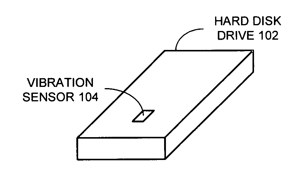
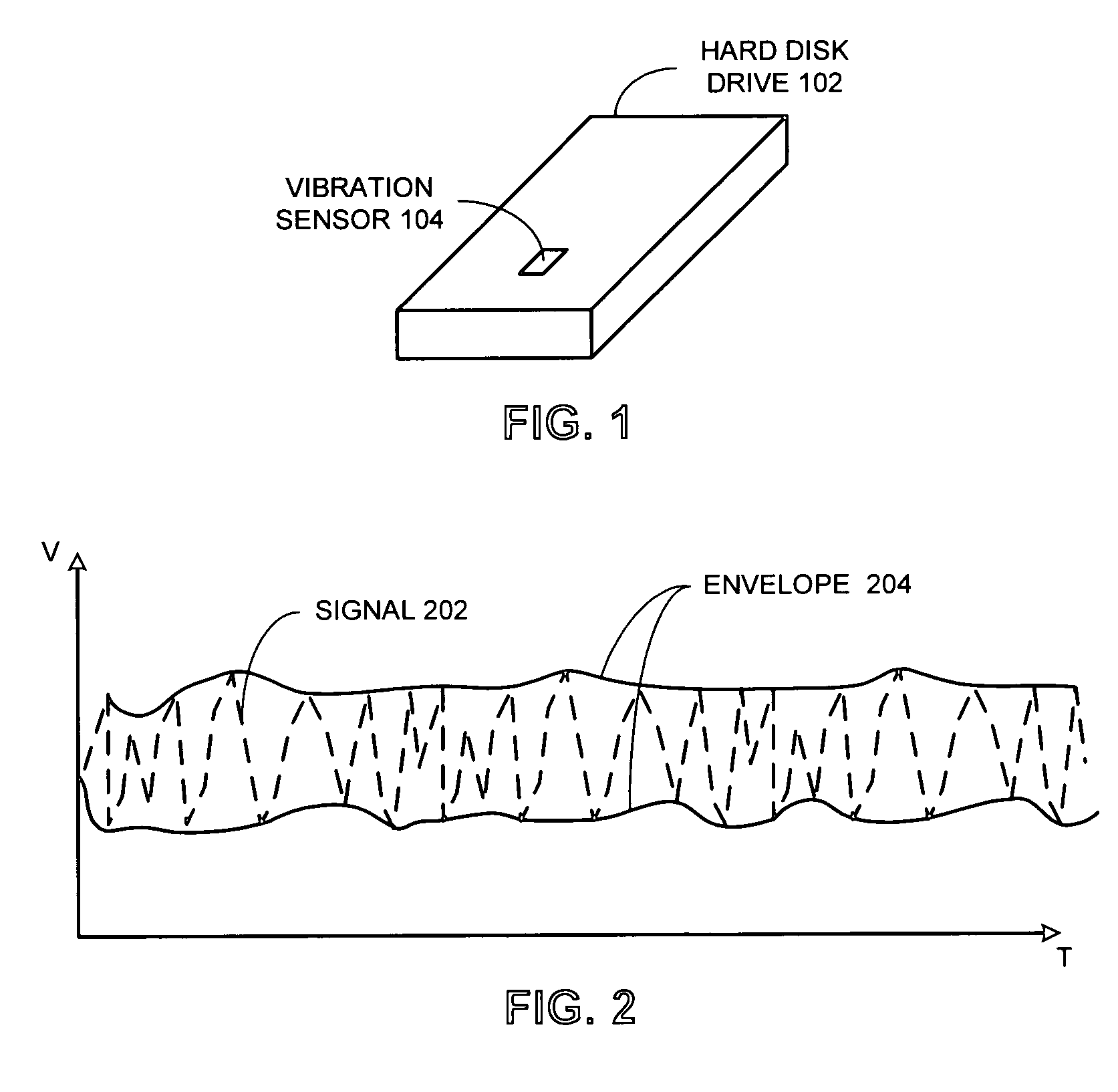
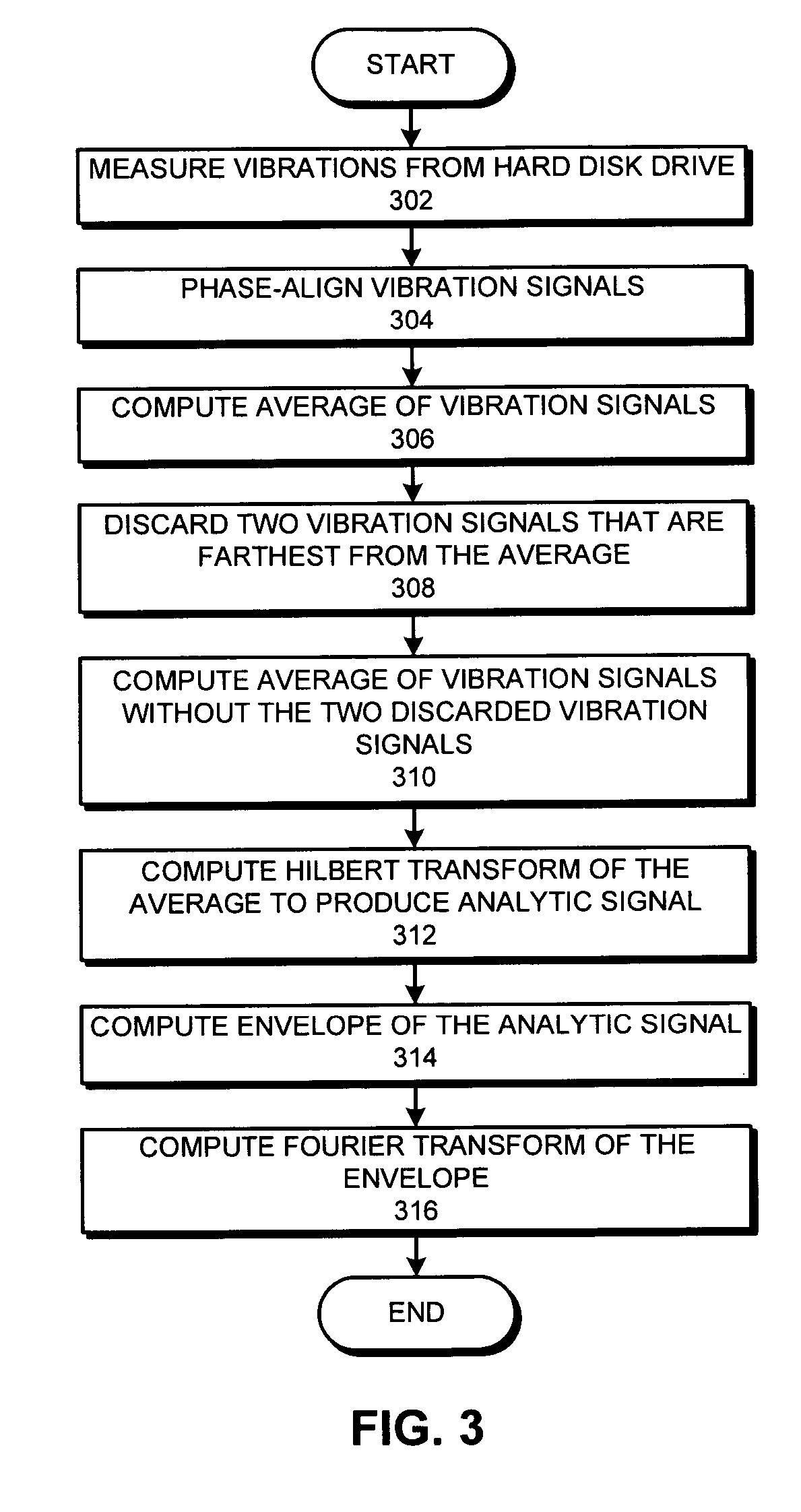
[0011] One embodiment of the present invention provides a system that detects the onset of hard disk drive failure. During operation, the system measures vibrations from the hard disk drive to produce one or more vibration signals. Next, the system generates a vibration signature for the hard disk d

Problems solved by technology

Losing or corrupting data stored on disk drives can have a devastating effect on such businesses.
For example, airlines rely on the integrity of data stored in their reservation systems for most of their day-to-day operations, and would essentially cease to function if this data became lost or corrupted.
Unfortunately, these techniques suffer from a high missed-alarm probability (MAP) of 50%, and a false-alarm probability of 1% (FAP).
The high MAP causes an increased probability of massive data loss.
The FAP causes a large numbers of No-Trouble-Found (NTF) drives to be returned, resulting in increased warranty costs.
This technique usually monitors internal diagnostic counter-type variables called “SMART variables.” However, hard disk drive manufacturers are reluctant to add extra diagnostics to monitor these variables, because doing so increases the cost of the commodity hard disk drives.
Unfortunately, this technique also fails to identify approximately 50% of imminent hard disk drive failures.
Unfortunately, since the capacity of hard disk drives have increased dramatically in recent years, the time needed to rebuild a RAID disk after a failure of one of the disks has also increased dramatically.
The rebuild process can take many hours to several days, during which the system is susceptible to a second hard disk drive failure which would result in massive data loss.
Hence, even the most advanced redundancy-based solutions are susceptible to data loss.

Method used


Image

  • Method and apparatus for detecting the onset of hard disk failures
  • Method and apparatus for detecting the onset of hard disk failures
  • Method and apparatus for detecting the onset of hard disk failures

Examples


Embodiment Construction

[0023] The following description is presented to enable any person skilled in the art to make and use the invention, and is provided in the context of a particular application and its requirements. Various modifications to the disclosed embodiments will be readily apparent to those skilled in the art, and the general principles defined herein may be applied to other embodiments and applications without departing from the spirit and scope of the present invention. Thus, the present invention is not limited to the embodiments shown, but is to be accorded the widest scope consistent with the principles and features disclosed herein.

[0024] The data structures and code described in this detailed description are typically stored on a computer-readable storage medium, which may be any device or medium that can store code and / or data for use by a computer system. This includes, but is not limited to, magnetic and optical storage devices such as disk drives, magnetic tape, CDs (compact disc...


PUM


Abstract

A system that detects the onset of hard disk drive failure. During operation, the system measures vibrations from the hard disk drive to produce one or more vibration signals. Next, the system generates a vibration signature for the hard disk drive from the measured vibration signals. The system then determines if the vibration signature indicates the onset of hard disk failure by comparing the vibration signature with a reference vibration signature for the hard disk drive. If so, the system generates a warning or takes a remedial action.

Description

RELATED APPLICATION [0001] This application is a continuation-in-part of, and hereby claims priority under 35 U.S.C.§ 120 to U.S. patent application Ser. No. 10 / 222,611, entitled “Method And Apparatus For Using Acoustic Signals To Identify Disk Drives That Are Likely To Fail,” by inventors Kenny C. Gross and Wendy Lu, filed on 16 Aug. 2002 (Attorney Docket No. SUN-P8402-SPL). Furthermore, the above-listed application is hereby incorporated by reference herein to provide details of how to identify a failing disk drive by analyzing the acoustical frequency signature of the disk drive.BACKGROUND [0002] 1. Field of the Invention [0003] The present invention relates to techniques for providing fault-tolerance in computer systems. More specifically, the present invention relates to a method and apparatus for using vibration signatures to detect the onset of hard disk drive failures. [0004] 2. Related Art [0005] As computer systems are becoming more powerful, they are increasingly being us...

Claims


Application Information

Patent Timeline
IPC IPC(8): G06F11/00G01H1/00G06F11/07G11B20/18G11B27/36
CPCG01H1/003G06F11/0727G06F11/0751G11B5/40G11B2220/415G11B20/1816G11B27/36G11B2220/2516G11B19/04
Inventor URMANOV, ALEKSEY M.GROSS, KENNY C.
Owner ORACLE INT CORP
Learn More