Electromechanical switching device

a switching device and electromechanical technology, applied in circuit-breaking switches, magnets, magnetic bodies, etc., can solve the problems of restricted fitting space, relatively expensive manufacturing of special components, and inability to install special components

Inactive Publication Date: 2006-09-28
SIEMENS AG
View PDF1 Cites 3 Cited by
  • Summary
  • Abstract
  • Description
  • Claims
  • Application Information

AI Technical Summary

Benefits of technology

[0014] Relative to an axis disposed normally to the housing fixing side the circuit arrangement of second immediate-response and second delayed-response actuator is essentially rotated through 180° relative to the circuit arrangement of first immediate-response and second delayed-response actuator. The particular advantage of the restricted or opposite arrangement of the individual actuators in the h...

Problems solved by technology

In each case, where there is provision for installing a larger number of individual components compared to a switching device with an undivided housing of the corresponding size, the result ...

Method used


Image

  • Electromechanical switching device
  • Electromechanical switching device
  • Electromechanical switching device

Examples


Embodiment Construction

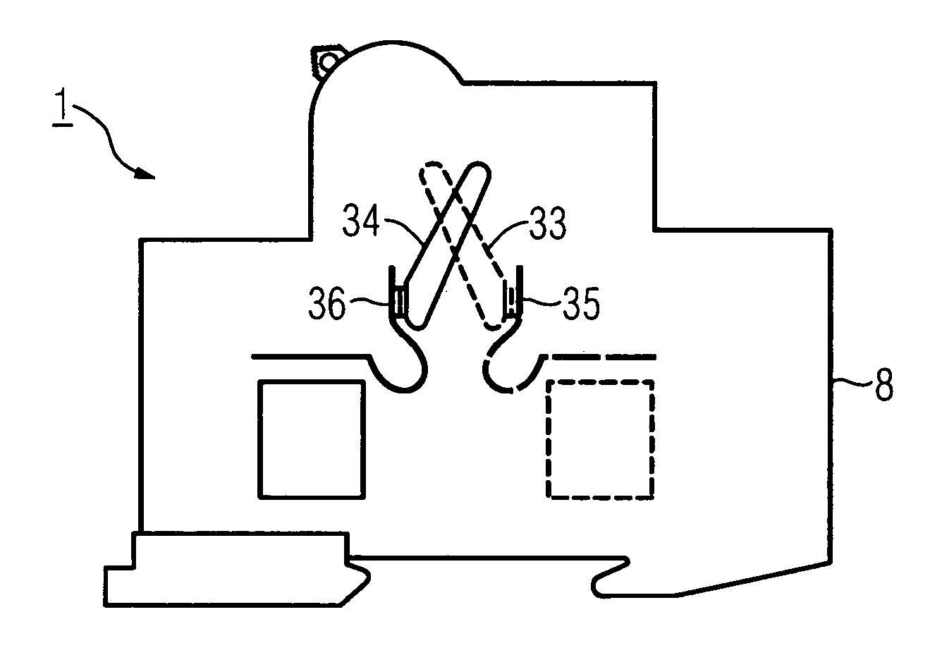
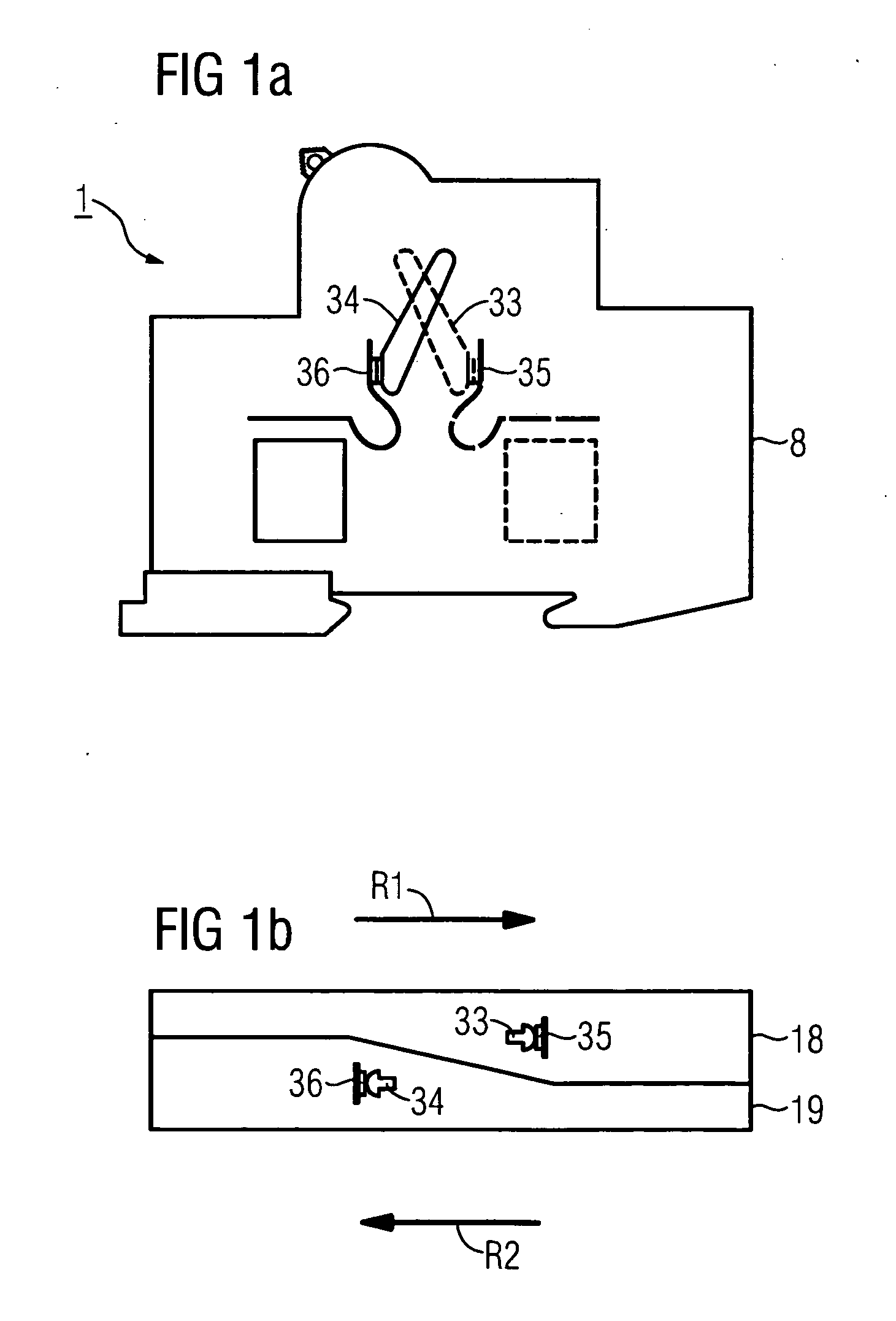
[0023]FIGS. 1a and 1b show symbolically in lengthwise section or cross section an electromechanical switching device 1 as a series built-in device in which two current paths are switched. To this end switching device 1 features a housing 8, which is subdivided lengthwise into a first housing area 18 and a second housing area 19. In each of the housing areas 18,19, for switching a current path there is a movable contact element 33,34 and a fixed contact 35,36 which interacts with it in each case. The first movable contact 33 arranged in the first housing area 18 is movable in a direction of actuation R1 in the direction of the assigned first fixed contact 35, while the second movable contact 34 in the second housing area 19 is movable in the opposite direction of actuation R2 to close the corresponding current path to the second fixed contact 36. The movable contacts 33,34 are for example able to be actuated manually or electromagnetically. As regards further possible details of the ...


PUM


Abstract

The invention relates to a electromechanical switching device having two movable contact elements interacting with a fixed contact. Said switching device has a housing. When viewing a fixing side from the top, said housing is divided into two areas bordering with a longitudinal side of the housing, one of the movable contact elements and the corresponding fixed contact being located in said areas, wherein each of the housing areas has a narrow partial area and a broad partial area bordering therewith. The broad partial area of the first housing area is adjacent to the narrow partial area of the second housing area and the narrow partial area of the first housing area is adjacent to the broad partial area of the second housing area. The actuation directions of the movable contact elements are directed opposite each other.

Description

CROSS REFERENCE TO RELATED APPLICATIONS [0001] This application is the US National Stage of International Application No. PCT / EP2004 / 003536, filed Apr. 2, 2004 and claims the benefit thereof. The International Application claims the benefits of European application No. 03009941.0, filed Apr. 30, 2003, both applications are incorporated by reference herein in their entirety.FIELD OF INVENTION [0002] The invention relates to a electromechanical switching device, especially an electromagnetic switching device, having at least two movable contact elements interacting with a fixed contact, which are arranged in adjacent areas of a housing subdivided into a number of areas. SUMMARY OF THE INVENTION [0003] An electromagnetic switching device with a divided housing, in which subareas each switch one current track, is for example known from DE 32 42 062 C2. Electromagnetic actuators as well as a thermal actuator are arranged in a first part of the housing featuring a first contact point. A s...

Claims


Application Information

Patent Timeline
IPC IPC(8): H01F7/08H01H71/00H01H71/02
CPCH01H71/002H01H71/025
Inventor ECKERT, GUNTHERLEITL, WOLFGANG
Owner SIEMENS AG
Why Eureka
Try Eureka