Method of chemically decontaminating components of radioactive material handling facility and system for carrying out the same

Inactive Publication Date: 2005-04-05
KK TOSHIBA
View PDF18 Cites 20 Cited by
  • Summary
  • Abstract
  • Description
  • Claims
  • Application Information

AI Technical Summary

Benefits of technology

The present invention has been made to solve the foregoing problems and it is therefore an object of the present invention to provide a chemical decontamination method and a system for carrying out the same

Problems solved by technology

Oxide films containing radioactive nuclides are deposited or formed on the surfaces of components of a nuclear power station in contact with fluids containing radioactive nuclides during operation and subject to radioactive contamination, such as pipes, pieces of equipment and structural members.
Consequently, the dose rate around those component members increases and the radiation exposure of workers engaged in work for periodic inspection or dismantlement of a nuclear reactor for decommissioning.
However, the ozone concentration of ozone gas produced by a conventional silent discharge ozonizer is low (in general, lower than 1% by volume), and the ozone concentration of ozone solution prepared by supplying the ozone gas in an acid solution is several parts per million or less.
An oxidation process using an ozone soluti

Method used


Image

  • Method of chemically decontaminating components of radioactive material handling facility and system for carrying out the same
  • Method of chemically decontaminating components of radioactive material handling facility and system for carrying out the same
  • Method of chemically decontaminating components of radioactive material handling facility and system for carrying out the same

Examples


Example

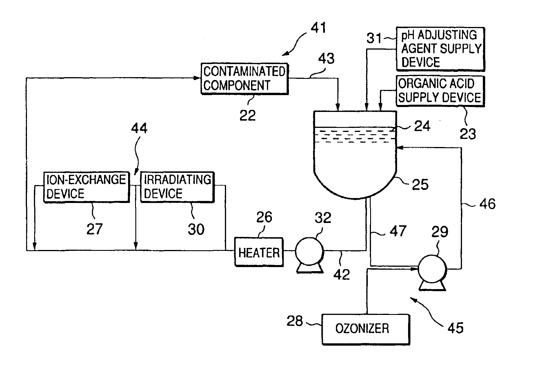
Referring to FIG. 15 showing a chemical decontamination system in a first embodiment according to the present invention, a contaminated object 22 is, for example, a pipe of a nuclear reactor or an in-pile device, such as a heat exchanger, through which a decontaminating liquid 24 can flow.

The decontaminating liquid 24 is stored in a buffer tank 25. A decontaminating liquid circulating system 41 is connected to the buffer tank 25 to circulate the decontaminating liquid 24 through the contaminated object 22.

The decontaminating liquid circulating system 41 has a supply line 42 connected to the bottom of the buffer tank 25 to supply the decontaminating liquid 24 to the contaminated object 22, and a return line 43 connected to the upper end of the buffer tank 25 to return the decontaminating liquid passed through the contaminated object 22 to the buffer tank 25.

A circulating pump 32, a heater 26, and a decontaminating liquid purifying system 44 provided with an irradiating device 30 and ...

Example

A chemical decontamination system in a second embodiment according to the present invention will be described with reference to FIG. 16. This chemical decontamination system is intended for decontaminating a shroud 33 installed in a pressure vessel for a nuclear reactor, a reactor coolant recirculating line 48 connected to the shroud 33, and a recirculating pump 49 disposed in the primary coolant recirculating line 48 as contaminated objects. The second embodiment is characterized in using the shroud 33 having the shape of a vessel as a buffer tank.

A decontaminating liquid circulating system 41 similar to that shown in FIG. 15 is connected to the shroud 33. The decontaminating liquid circulating system 41 may be connected to the shroud 33 by using a fixture, not shown, included in the primary coolant recirculating line 48. The decontaminating liquid circulating system 41, similarly to that shown in FIG. 15, comprises a heater 26, an ozone injecting system 45 and a decontaminating li...

Example

A chemical decontamination system in a third embodiment according to the present invention will be described with reference to FIG. 18. This chemical decontamination system is intended for the decontamination of the inner surfaces of a coolant circulating pump 34 and a riser pipe 35 included in a boiling water reactor installed in a nuclear power plant. The riser pipe 35 has a horizontal section and vertical sections rising from the opposite ends, respectively, of the horizontal section. A pump 34 is connected to the horizontal section of the riser pipe 35.

The horizontal section of the riser pipe 35 is provided with a first connecting part 36 and a second connecting part 38 at positions on the opposite sides of the pump 34. The connecting parts 36 and 38 are connected to the opposite ends of a line of a decontaminating liquid purifying system 44, respectively. A decontaminating liquid circulating system 41, similarly to that shown in FIG. 15, comprises a heater 26, an ozone injectin...


PUM


Abstract

Ozone gas having a high ozone concentration is generated by a solid electrolyte electrolytic process. An ozone solution is prepared by injecting the ozone gas into an acidic solution of pH 6 or below. The ozone solution heated at a temperature in the range of 50° to 90° C. is supplied to a contaminated object to oxidize and dissolve a chromium oxide film by an oxidizing dissolving process. The ozone solution used in the oxidizing dissolving process is irradiated with ultraviolet rays to decompose ozone contained in the ozone solution, the ozone solution is passed through an ion-exchange resin to remove ions contained in the ozone solution. An oxalic acid solution is supplied to the contaminated object to dissolve an iron oxide film by a reductive dissolving process. Oxalic acid remaining in the oxalic acid solution after the reductive dissolving process is decomposed by injecting ozone into the oxalic acid solution and irradiating the oxalic acid solution with ultraviolet rays, and ions contained in the oxalic acid solution is removed by an ion-exchange resin.

Description

BACKGROUND OF THE INVENTION1. Field of the InventionThe present invention relates to a method of chemical decontamination for the components of a radioactive material handling facility, such as a nuclear power station, and a system for carrying out the method of removing metal oxides containing radioactive nuclides and adhering to the components of the radioactive material handling facilities from the surfaces of the contaminated components by chemical dissolution.2. Description of the Related ArtOxide films containing radioactive nuclides are deposited or formed on the surfaces of components of a nuclear power station in contact with fluids containing radioactive nuclides during operation and subject to radioactive contamination, such as pipes, pieces of equipment and structural members. Consequently, the dose rate around those component members increases and the radiation exposure of workers engaged in work for periodic inspection or dismantlement of a nuclear reactor for decommis...

Claims


Application Information

Patent Timeline
IPC IPC(8): B08B3/00C25B11/00C25B11/04C25D17/00G21F9/00C25B9/23
CPCC25B1/13G21F9/004G21F9/002C25B9/10C25B9/23
Inventor YAITA, YUMIENDA, MASAMISAKAI, HITOSHI
Owner KK TOSHIBA
Why Eureka
Try Eureka