
Liquid ejection apparatus, inkjet recording apparatus and liquid removal method

Inactive Publication Date: 2006-09-28
FUJIFILM CORP
View PDF4 Cites 17 Cited by
  • Summary
  • Abstract
  • Description
  • Claims
  • Application Information

AI Technical Summary

Benefits of technology

[0013] According to the present invention, when removing the liquid that has been ejected onto the liquid receiving medium, the liquid removal device is placed in contact with the liquid, and when not removing the liquid that has been ejected onto the liquid receiving medium, the liquid removal device is moved so that it does not make contact with the liquid. Therefore, soiling of the liquid receiving medium due to the liquid removal device making contact with the liquid receiving medium is prevented, and furthermore, wearing and deformation of the liquid removal device is suppressed, and increased lifespan of the liquid removal device can be achieved. Furthermore, since it is determined whether or not to perform liquid removal on the basis of the ejection volume of the liquid ejected onto the liquid receiving medium, then it is possible to remove the liquid efficiently in accordance with the liquid volume on the liquid receiving medium.
[0049] According to the present invention, the distance between the liquid ejection device and the liquid receiving medium is controlled in such a manner that the liquid removal device which removes liquid on the liquid receiving medium makes contact with the liquid on the liquid receiving medium when performing liquid removal, and the liquid removal device does not make contact with the liquid on the liquid receiving medium when not performing liquid removal. Therefore, it is possible to extend the lifespan of the liquid removal device, as well as preventing soiling of the liquid receiving medium due to contact between the liquid removal device and the liquid receiving medium.

Problems solved by technology

When the ink solvent remaining on the medium makes contact with another medium, it may give rise to soiling of the recorded image.
Furthermore, the ink solvent remaining on the medium may be a cause of cockling of the medium.
When the solvent remaining on the medium is removed by applying heat to the medium by means of a heater, it is difficult to remove solvent from a specific region of the medium, and it is also difficult to control the amount of heat applied to the medium from the heater, in accordance with the volume of the remaining solvent.
In the ink absorbing body and the image forming apparatus and the method using the ink absorbing body as described in Japanese Patent Application Publication No. 2001-179959, and the transfer type inkjet printer as described in Japanese Patent Application Publication No. 6-126945, a composition is adopted in which the medium makes contact with the ink absorbing body even when removal of the ink solvent is not required, and hence there is a probability that soiling on the ink absorbing body adheres to the medium, thereby degrading the image formed on the medium.
Furthermore, there is also a probability that the ink absorbing body may deform if the ink absorbing body makes contact with the medium for a prolonged period of time, and hence there are concerns regarding decline in the ink solvent removal capability.

Method used


Image

  • Liquid ejection apparatus, inkjet recording apparatus and liquid removal method
  • Liquid ejection apparatus, inkjet recording apparatus and liquid removal method
  • Liquid ejection apparatus, inkjet recording apparatus and liquid removal method

Examples


Embodiment Construction

General Composition of Inkjet Recording Apparatus

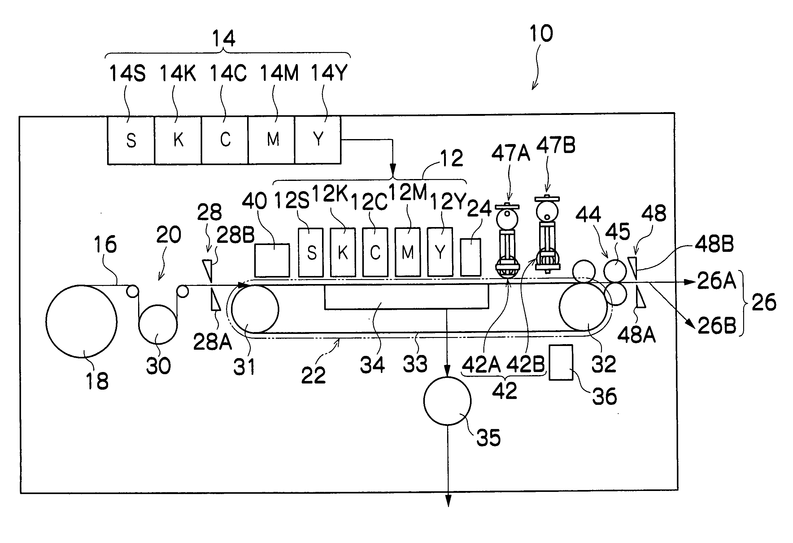
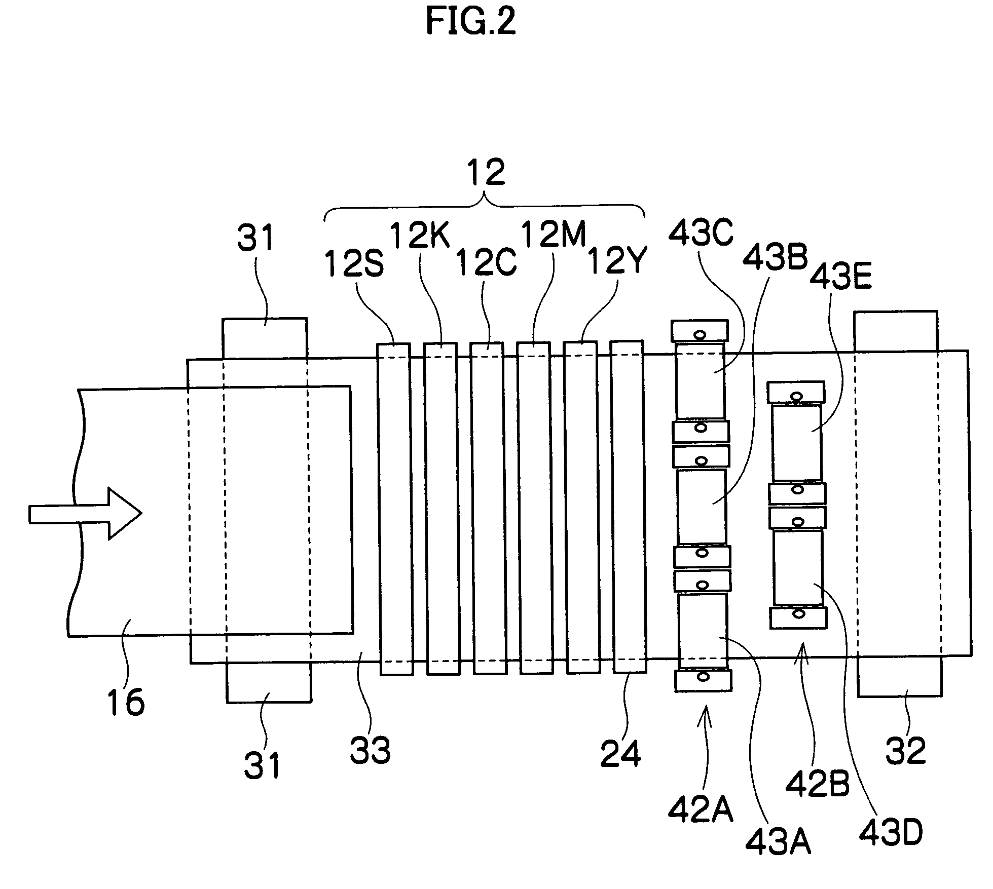
[0070]FIG. 1 is a diagram of the general composition of an inkjet recording apparatus according to an embodiment of the present invention. As shown in FIG. 1, the inkjet recording apparatus 10 comprises: a print unit 12 having a plurality of print heads 12K, 12C, 12M and 12Y provided for respective inks of the colors black (K), cyan (C), magenta (M) and yellow (Y); a treatment liquid ejection head 12S, which ejects treatment liquid reacting with the ink, arranged in a stage prior to the print heads 12K, 12C, 12M and 12Y (hereinafter, the print heads 12K, 12C, 12M and 12Y and the treatment liquid ejection head 12S are referred to generally as the heads 12S, 12K, 12C, 12M and 12Y); a storing and loading unit 14, which stores the ink to be supplied to the print heads 12K, 12C, 12M and 12Y of the respective colored inks, and the treatment liquid to be supplied to the treatment liquid ejection head 12S; a paper supply unit 18, which supp...


PUM


Abstract

The liquid ejection apparatus comprises: a liquid ejection head which ejects liquid onto a liquid receiving medium; a conveyance device which conveys the liquid receiving medium in a conveyance direction relatively to the liquid ejection head, by moving at least one of the liquid receiving medium and the liquid ejection head; a liquid removal device which is arranged on a downstream side of the liquid ejection head in the conveyance direction and removes the liquid on the liquid receiving medium; a movement device which varies a distance between the liquid removal device and the liquid receiving medium, by moving the liquid removal device; an ejection volume determination device which determines a liquid ejection volume being a volume of the liquid ejected on the liquid receiving medium; and a liquid removal control device which determines whether or not to carry out liquid removal from the liquid receiving medium in accordance with the liquid ejection volume determined by the ejection volume determination device, and implements control for moving the liquid removal device in such a manner that the liquid removal device is placed in contact with the liquid on the liquid receiving medium if the liquid on the liquid receiving medium is to be removed, and the liquid removal device is not placed in contact with the liquid on the liquid receiving medium if the liquid on the liquid receiving medium is not to be removed.

Description

BACKGROUND OF THE INVENTION [0001] 1. Field of the Invention [0002] The present invention relates to a liquid ejection apparatus, an inkjet recording apparatus and a liquid removal method, and more particularly, to liquid removal technology which efficiently removes surplus liquid on a liquid receiving medium. [0003] 2. Description of the Related Art [0004] In recent years, inkjet recording apparatuses have come to be used widely as data output apparatuses for outputting images, documents, or the like. An inkjet recording apparatus forms an image, document, or the like, corresponding to data, on a recording medium by ejecting ink from nozzles, by driving actuators corresponding to nozzles provided in a print head, in accordance with data. [0005] In an inkjet recording apparatus, since a liquid ink is used in which coloring material and additives are included in a solvent, such as water or alcohol, then the ink (ink solvent) remains on the medium after image formation. When the ink s...

Claims


Application Information

Patent Timeline
IPC IPC(8): B41J29/38B41J23/00B41J2/01
CPCB41J11/0015B41J29/393B41M7/00
Inventor INOUE, HIROSHI
Owner FUJIFILM CORP
Learn More