Method of Testing a Droplet Discharge Device

a technology of droplet discharge and droplet, which is applied in the direction of printing, other printing apparatus, etc., can solve the problems of inaccurate detection of inability to accurately detect the position of the nozzle, and inability to test how much the nozzle position deviates from the designed position, etc., and achieve the effect of accurate determination

Active Publication Date: 2006-09-28
BROTHER KOGYO KK
View PDF2 Cites 43 Cited by
  • Summary
  • Abstract
  • Description
  • Claims
  • Application Information

AI Technical Summary

Benefits of technology

[0018] With this testing method, the nozzle and liquid adhering to the test sheet need not be photographed from the rear side of the test sheet with a CCD camera. The test sheet therefore need not be transparent. The test sheet to be used ca

Problems solved by technology

If the liquid does not optimally adhere to the test sheet, the position of liquid adherence cannot be accurately detected.
Moreover, if the transparent test sheet is not provided flatly, the CCD camera cannot accu

Method used


Image

  • Method of Testing a Droplet Discharge Device
  • Method of Testing a Droplet Discharge Device
  • Method of Testing a Droplet Discharge Device

Examples


first embodiment

of the Invention

[0057] A first embodiment of an inkjet head test method of the invention is discussed here.

Inkjet Head

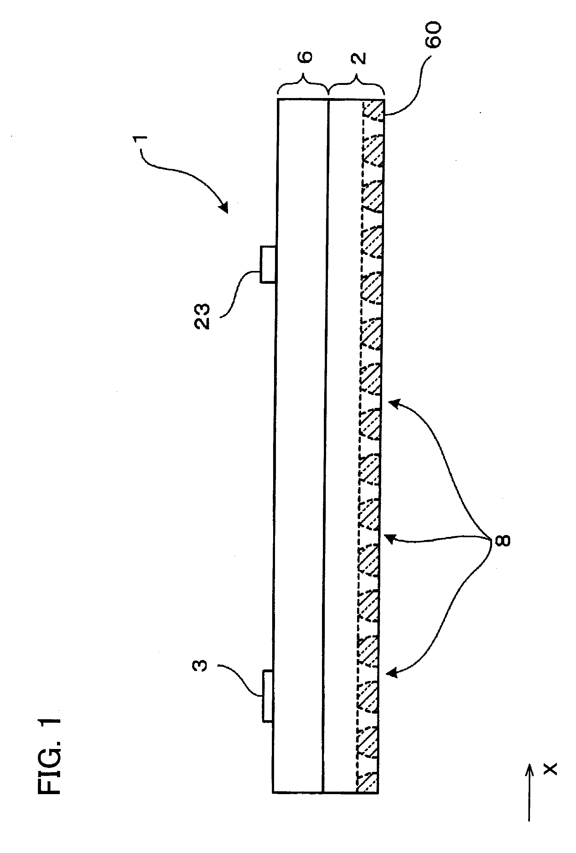
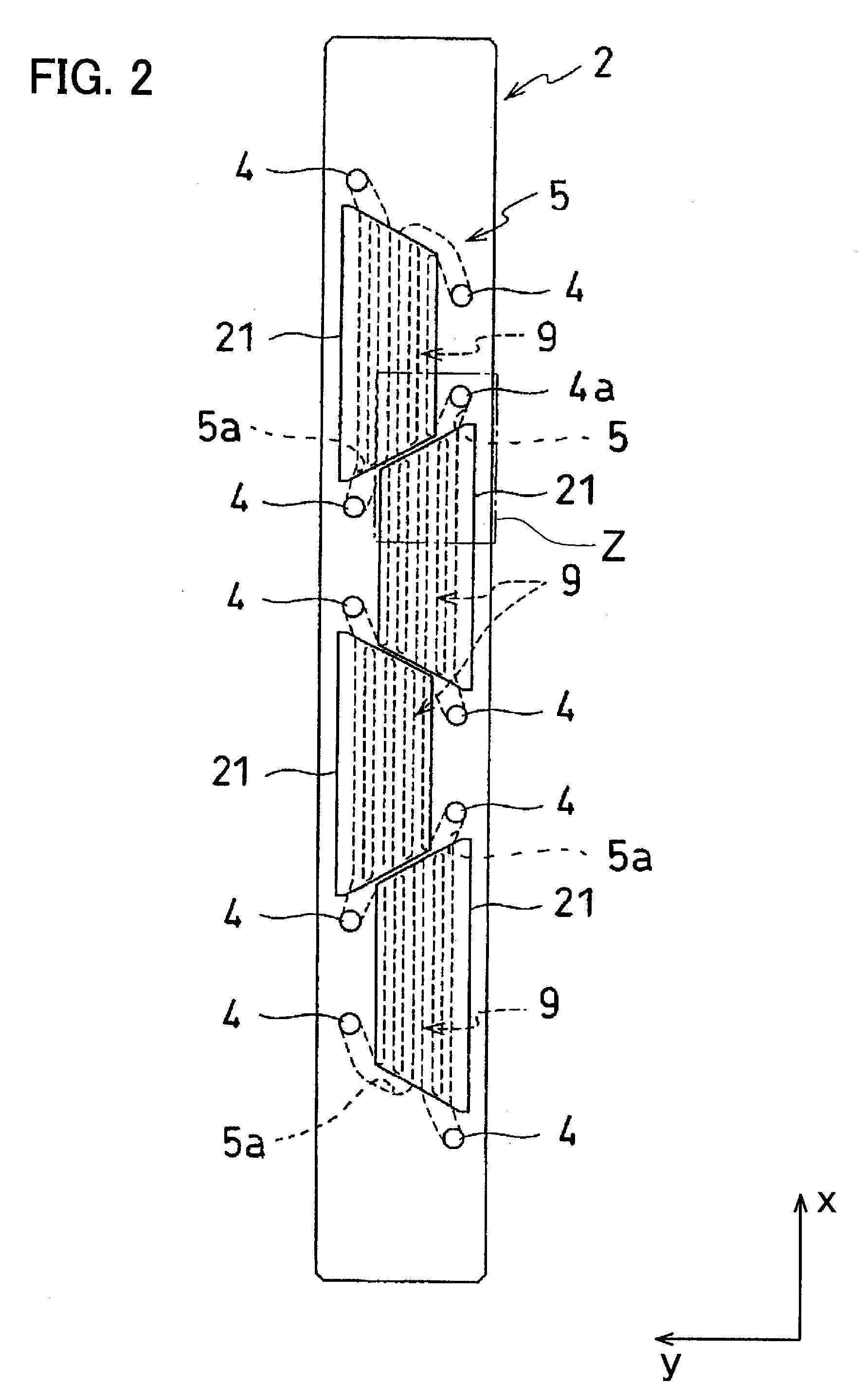
[0058]FIG. 1 is a side view of inkjet head 1 to be tested with the present testing method. Inkjet head 1 is an elongated shape in the x direction in FIG. 1. When printing is accomplished with inkjet head 1, printing paper is provided on the lower side of lower surface 60 of inkjet head 1. Given that the direction from in front of to behind the plane of the page of FIG. 1 is the y direction, the printing paper is sent in the y direction. Inkjet head 1 comprises flow channel unit 2 that discharges ink, ink supply unit 6 that guides ink to flow channel unit 2, and four actuator units 21 (FIG. 2).

[0059] Ink supply port 3 is formed on the upper portion of ink supply unit 6. Ink is supplied from outside through ink supply port 3. Some ink flow channels are formed within ink supply unit 6. One end of the ink flow channels is connected to ink supply port 3. The other end...

second embodiment

of the Invention

[0137] A second embodiment of an inkjet head test method of the invention is discussed here. The second embodiment contains many steps and components common to the first embodiment, so descriptions thereof are omitted when appropriate. In the testing method of an inkjet head of the second embodiment, test pattern printing device 124 that is shown in FIG. 16 and test pattern measuring device 161 that is shown in FIG. 17 are used. In the testing method of the second embodiment, position errors and discharge angle errors of nozzles 8 are assessed.

[0138] The test pattern printing device 124 shown in FIG. 16 prints test patterns on printing paper 22 that is provided with marker 101 as shown in FIG. 16. Marker 101 is provided at a specified position on the recording surface of printing paper 22. Marker 101, which is a thin, rectangular sheet, is, as FIG. 16 shows, very small relative to printing paper 22.

[0139] The composition of test pattern printing device 124 of the s...

third embodiment

of the Invention

[0154]FIG. 19 shows test pattern printing device 224 of the third embodiment of the invention. The composition of test pattern printing device 224 of the third embodiment is similar to the composition of test pattern printing device 24 of the first embodiment. Test pattern printing device 224, however, comprises marker attaching unit 200 absent in test pattern printing device 24.

[0155] Marker affixing unit 200 is vertically movable relative to a fixed position of head securing plate 27. Inkjet head 1 is also secured to head securing plate 27. Therefore, inkjet head 1 and marker affixing unit 200 are secured at a certain positional relationship in the x and y directions. Marker affixing unit 200 is impelled upward by a spring and stops with a gap between the tip thereof and printing platform 29. Marker affixing unit 200 is manually or otherwise pressed downward to move the marker affixing unit 200 in the downward direction. An ink discharge port is formed on the lowe...


PUM


Abstract

A test sheet is set in a droplet discharge device at a first distance. At least one droplet is discharged toward the test sheet from a nozzle formed in the droplet discharge device to form at least one first dot on the test sheet. The test sheet is set in the droplet discharge device at a second distance differing from the first distance. At least one droplet is discharged toward the test sheet from the nozzle to form at least one second dot on the test sheet. A nozzle position error or a nozzle discharge angle error are calculated from the position of the first dot, the position of the second dot, the first distance, and the second distance. Testing inkjet heads in this manner allows accurate testing for errors in nozzle position or discharge angle.

Description

CROSS-REFERENCE TO RELATED APPLICATION [0001] This application claims priority to Japanese Patent Application No. 2005-083758 filed on Mar. 23, 2005, the contents of which are hereby incorporated by reference into the present application. BACKGROUND OF THE INVENTION [0002] 1. Field of the Invention [0003] The invention relates to a method of testing a droplet discharge device. [0004] 2. Description of the Related Art [0005] Inkjet heads and other droplet discharge devices are widely known. Droplet discharge devices discharge droplets from a nozzle and cause a liquid to accurately adhere to a target position. So that the liquid accurately adheres to the target position, the nozzle must be formed in a position as designed, and the droplet discharge device must be manufactured so that the droplet is discharged from the nozzle in the direction of the design. Therefore, the position of the nozzle of the droplet discharge device, the discharge angle of the droplets discharged from the noz...

Claims


Application Information

Patent Timeline
IPC IPC(8): B41J29/393
CPCB41J29/393B41J2/04526B41J2029/3935B41J2/04558
Inventor IWAO, NAOTOISHIKURA, SHIN
Owner BROTHER KOGYO KK
Why Eureka
Try Eureka