
Calculation of laser slope efficiency in an optical transceiver module

a technology of optical transceiver and laser, applied in the field of optical transceivers, can solve the problems of controllers, despite being partially effective, and the laser can exceed the acceptable range of such parameters, and achieve the effect of calculating the laser slope efficiency

Active Publication Date: 2006-09-28
II VI DELAWARE INC
View PDF4 Cites 25 Cited by
  • Summary
  • Abstract
  • Description
  • Claims
  • Application Information

AI Technical Summary

Benefits of technology

[0010] Briefly summarized, embodiments of the present invention are directed to systems and methods for determining and compensating for the slope efficiency of a light source, such as a directly-modulated laser, positioned in an optical transmitter in order to properly set a modulation current for the laser. In one embodiment, a method for setting a modulation current for the laser of an optical transmitter is disclosed wherein data relating to the laser transmit power and laser bias current at a plurality of laser bias current levels are sensed. A processor is then employed to calculate a slope efficiency of the laser using the data. The processor then determines a desired modulation current for the laser using the slope efficiency. Then if needed, the modulation current of the laser is modified to match the desired modulation current.
[0011] In another embodiment an optical transmitter device is disclosed. The device includes a transmitter optical subassembly having a laser, a plurality of sensors that sense data regarding bias current, modulation current, and transmit power of the laser, and a processor. The processor contains microcode that enables the processor to determine a slope efficiency of the laser using at least some of the data acquired by the plurality of sensors and to adjust the modulation current of the laser according to the determined slope efficiency.
[0012] In yet another embodiment a method for compensating for a slope efficiency of a laser in an optical transmitter is disclosed. The method includes varying a bias current of the laser to at least two bias current levels, sensing analog data relating to a transmit power and a bias current of the laser for the at least two bias current levels, converting the analog data to digital data, calculating a slope efficiency of the laser using the digital data, determining a desired modulation current for the laser according to the slope efficiency, and if needed, setting the modulation current for the laser according to the desired modulation current. This method is periodically repeated to ensure proper laser calibration.
[0013] These and other features of the present invention will become more fully apparent from the following description and appended claims, or may be learned by the practice of the invention as set forth hereinafter.

Problems solved by technology

Various factors can affect the operating parameters of a laser diode during its optical transmission activities, which can correspondingly cause the laser to exceed acceptable ranges for such parameters.
Should one or more parameters exceed predefined acceptable ranges, the optical signal produced by the laser can be adversely affected.
Such controllers, while partially effective, nonetheless suffer from various disadvantages.
Among the disadvantages is the fact that the compensation table used by the controller must be predefined during optical transmitter manufacture, and as such, is not capable of dynamic laser modification according to present operating requirements.
This can represent a significant expense in terms of manufacture time.
This operational variability over the life of the laser represents another challenge for maintaining the laser within proper operational parameter ranges.

Method used


Image

  • Calculation of laser slope efficiency in an optical transceiver module
  • Calculation of laser slope efficiency in an optical transceiver module
  • Calculation of laser slope efficiency in an optical transceiver module

Examples


Embodiment Construction

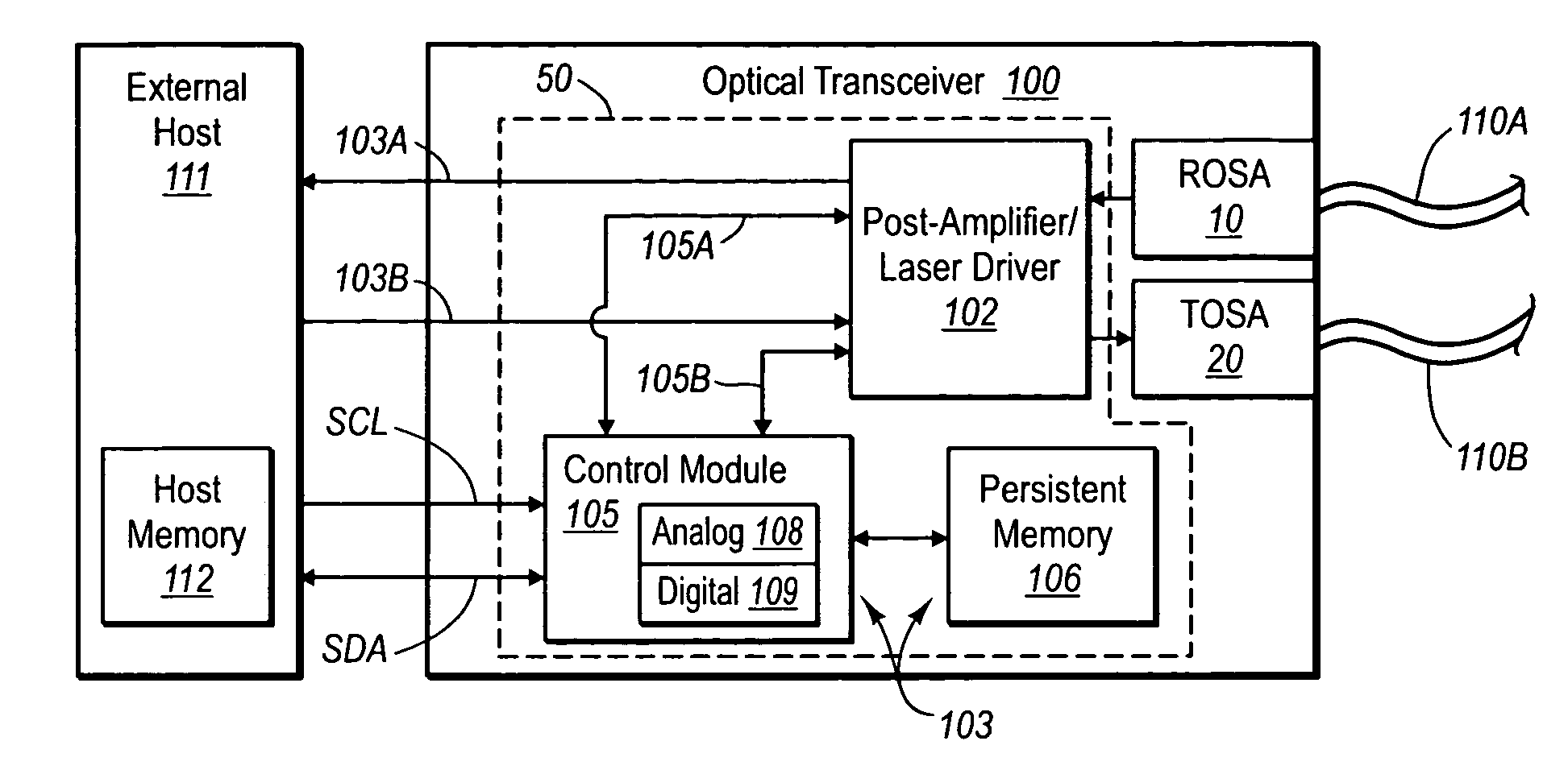
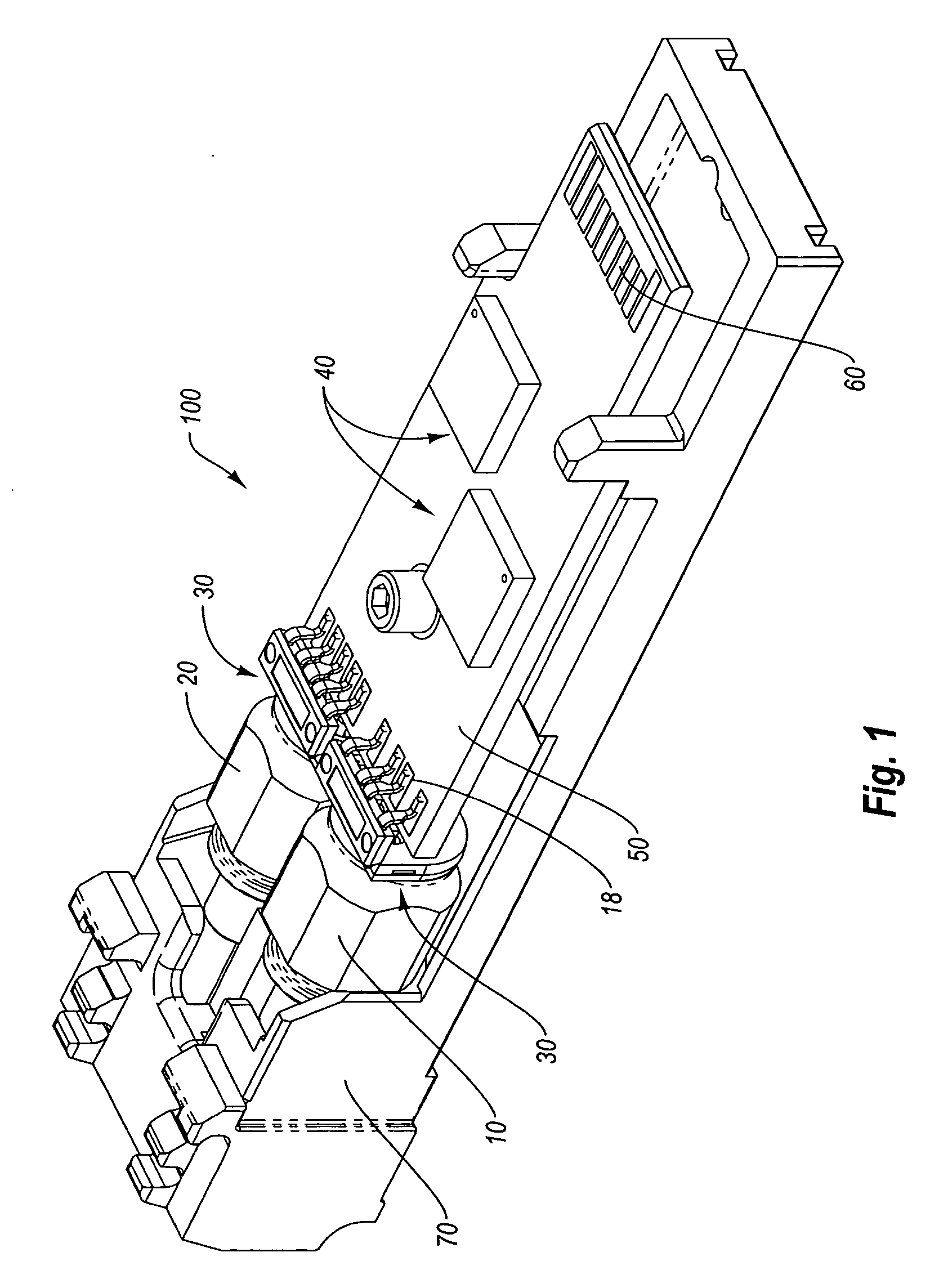
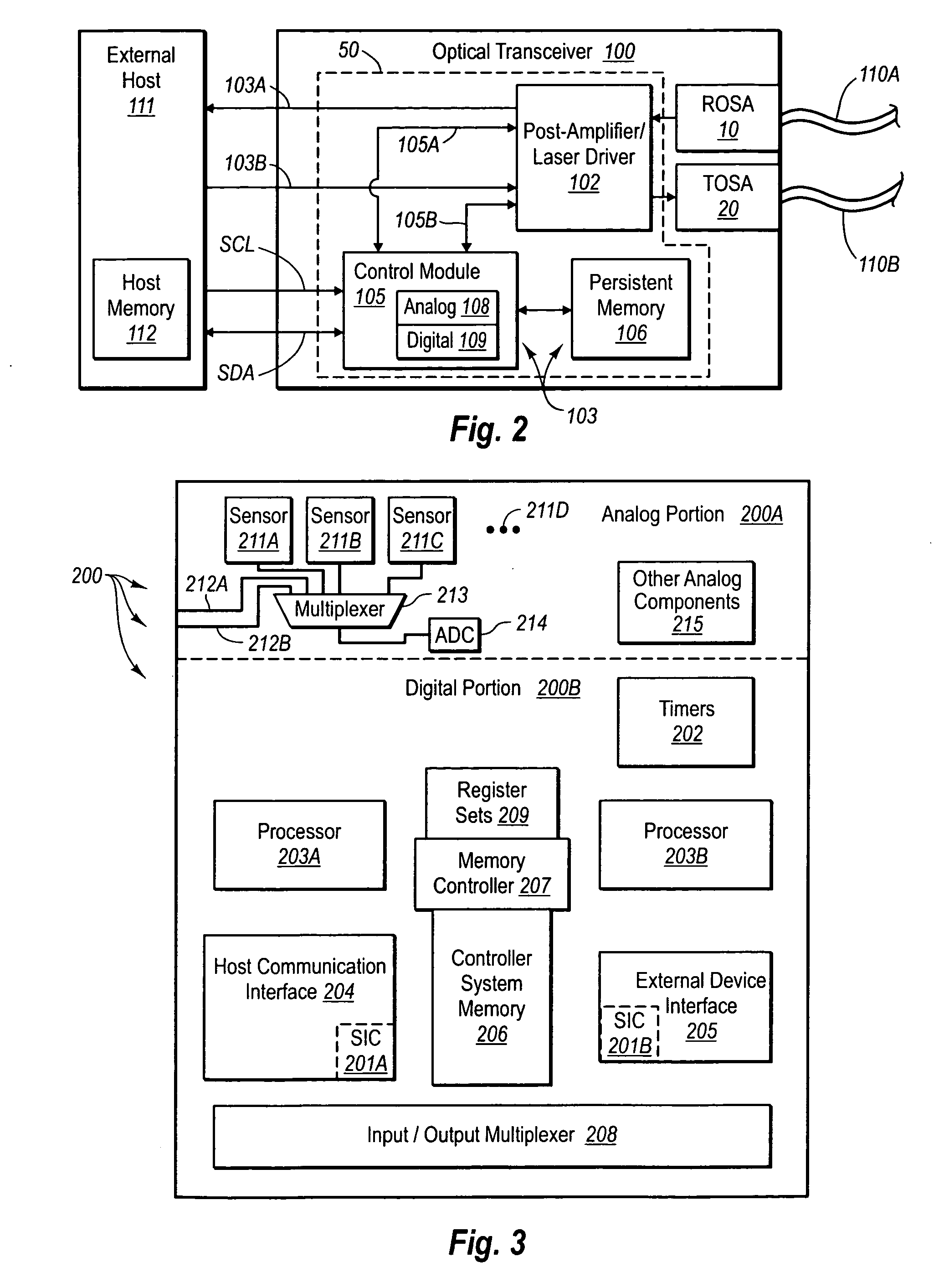
[0022] Reference will now be made to figures wherein like structures will be provided with like reference designations. It is understood that the drawings are diagrammatic and schematic representations of exemplary embodiments of the invention, and are not limiting of the present invention nor are they necessarily drawn to scale.

[0023]FIGS. 1-6 depict various features of embodiments of the present invention, which is generally directed to controlling a light source, such as a laser, in an optical transmitter, such as an optical transceiver module, according to data relating to slope efficiency of the light source during operation. In the exemplary embodiment, the laser is included in a transmitter optical subassembly (“TOSA”) of an optical transceiver module (“transceiver”). The TOSA, together with a receiver optical subassembly (“ROSA”) of the transceiver, include various components to enable the reception and transmission of optical signals to and from a host system that is opera...


PUM


Abstract

Systems and methods are provided for determining and compensating for the laser slope efficiency of a light source positioned in an optical transmitter in order to properly set a modulation current for the light source. In one embodiment, a method for setting a modulation current for the laser of an optical transmitter is disclosed, wherein data relating to the laser transmit power and laser bias current at a plurality of laser bias current levels are sensed. A processor is then employed to calculate a slope efficiency of the laser using the data. The processor then determines a desired modulation current for the laser using the slope efficiency. Then if needed, the modulation current of the laser is modified to match the desired modulation current.

Description

RELATED APPLICATIONS [0001] This application claims the benefit of U.S. Patent Application No. 60 / 664,016, entitled “Calculation of Laser Slope Efficiency in an Optical Transceiver Module,” filed on Mar. 22, 2005, which is incorporated herein by reference in its entirety.BACKGROUND [0002] 1. Technology Field [0003] The present invention generally relates to optical transmitters. In particular, the present invention relates to an optical device including an optical transmitter, wherein the optical device is capable of dynamically measuring and compensating for the laser slope efficiency of an optical signal produced and transmitted by the optical transmitter. [0004] 2. The Related Technology [0005] A properly operating light source is integral to functionality of an optical transmitter. Such light sources, including for example a laser diode positioned in a transmitter optical subassembly of an optical transceiver module, should conform to pre-defined parameters propounded by the man...

Claims


Application Information

Patent Timeline
Patent Type & Authority Applications(United States)
IPC IPC(8): H04B10/04
CPCH01S5/06812H01S5/06832H04B10/504H04B10/564
Inventor NELSON, STEPHEN T.
Owner II VI DELAWARE INC
Learn More