
Image forming method and apparatus capable of effectively positioning a cleaning unit

Active Publication Date: 2006-09-28
RICOH KK
View PDF6 Cites 11 Cited by
  • Summary
  • Abstract
  • Description
  • Claims
  • Application Information

AI Technical Summary

Benefits of technology

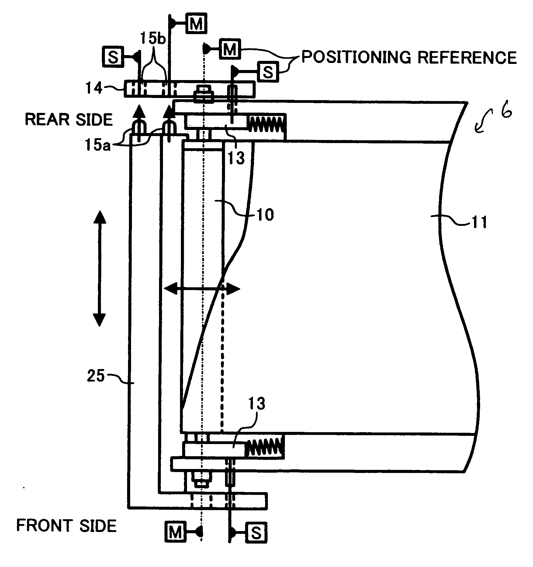
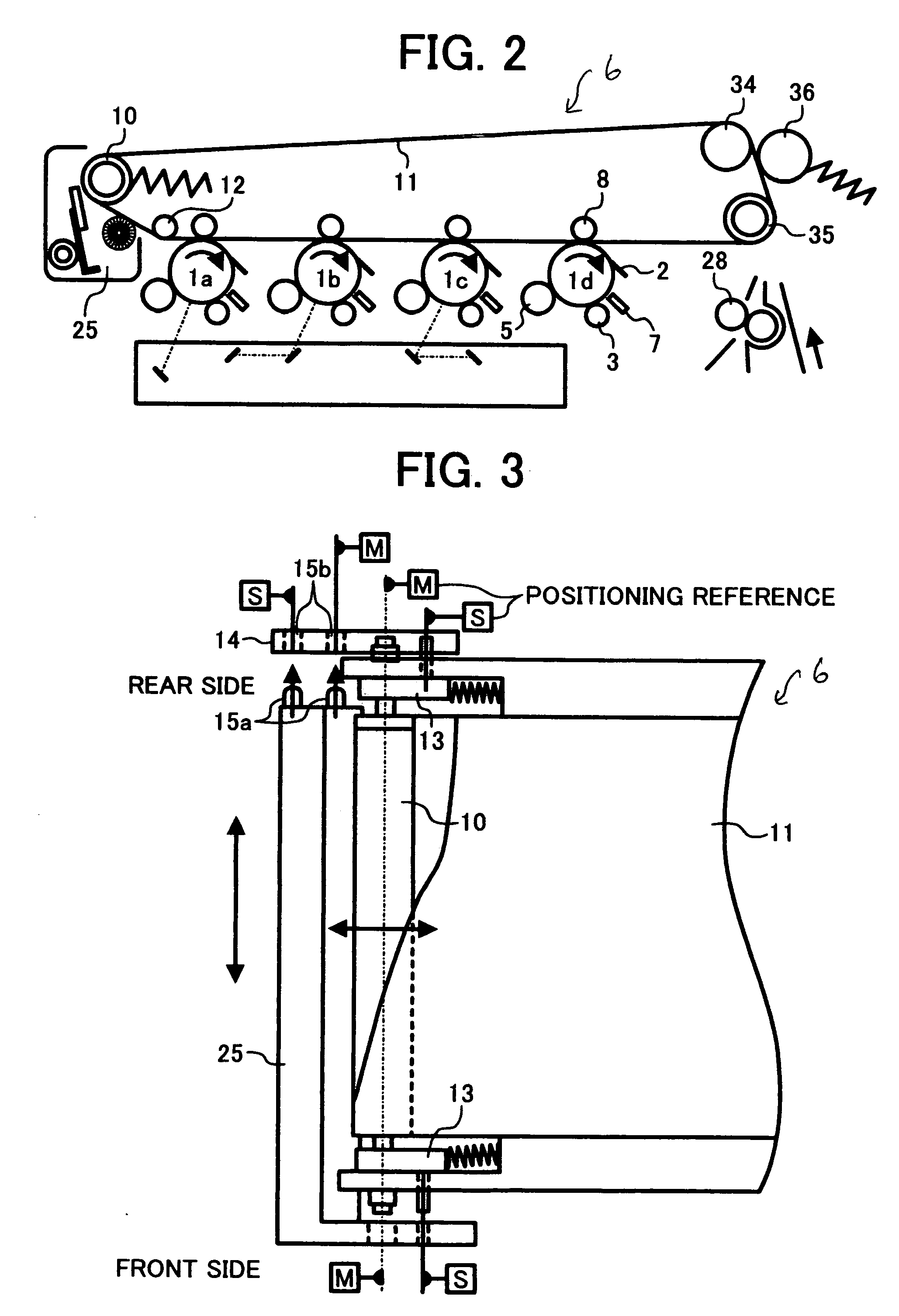
[0014] An object of the present invention is to provide a novel image forming apparatus that can prevent positioning error of a cleaning unit and provide an easy replacement thereof.
[0016] Another object of the present invention is to provide a novel cleaning unit having an engaging member to be engaged with an engaging member provided with the above-described novel image forming apparatus to be properly positioned to a positioning reference.

Problems solved by technology

However, the smaller particle diameter makes it more difficult to remove residual toner from an intermediate transfer belt.
Because of the presence of the plurality of photoconductive drums, space for other units becomes limited.
Thus, it is difficult to mount the cleaning member in an easily detachable manner to the image forming apparatus.
Furthermore, it is more difficult to position the cleaning member according to the tension roller in an axial direction of the tension roller.
However, the previously identified conventional approaches are deficient because they are prone to errors in positioning the cleaning unit.

Method used


Image

  • Image forming method and apparatus capable of effectively positioning a cleaning unit
  • Image forming method and apparatus capable of effectively positioning a cleaning unit
  • Image forming method and apparatus capable of effectively positioning a cleaning unit

Examples


Embodiment Construction

[0038] In describing preferred embodiments illustrated in the drawings, specific terminology is employed for the sake of clarity. However, the disclosure of this patent specification is not intended to be limited to the specific terminology so selected and it is to be understood that each specific element includes all technical equivalents that operate in a similar manner.

[0039] Referring now to the drawings, wherein like reference numerals designate identical or corresponding parts throughout the several views, preferred embodiments of the present invention are described.

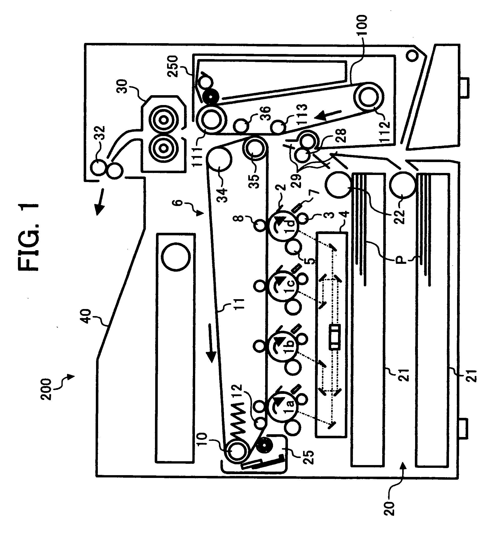
[0040] Referring to FIG. 1, a structure of an image forming apparatus 200 according to an exemplary embodiment of the present invention is described. The image forming apparatus 200 is a tandem-type image forming apparatus with an indirect system.

[0041] In FIG. 1, the image forming apparatus 200 includes four photoconductive elements 1a, 1b, 1c and 1d, serving as image bearing members. The four photoconductive e...


PUM


Abstract

An image forming apparatus and corresponding method, the apparatus including at least one image bearing member configured to bear an image, an intermediate transfer member configured to transfer the image formed on the at least one image bearing member, a roller configured to support the intermediate transfer member with tension, a cleaning unit disposed opposite to the roller and configured to remove residual toner from the intermediate transfer member, and is detachably disposed opposite to the roller, a holder configured to accommodate the roller, and a positioning member detachably mounted on the holder and configured to position the cleaning unit to a positioning reference.

Description

CROSS REFERENCE TO RELATED APPLICATIONS [0001] The present application claims priority to Japanese patent application no. 2005-080809, filed in the Japan Patent Office on Mar. 22, 2005, and Japanese patent application no. 2005-135683, filed in the Japan Patent Office on May 9, 2005, the disclosures of which are incorporated by reference herein in their entirety. BACKGROUND OF THE INVENTION [0002] 1. Field of the Invention [0003] The present invention relates to an image forming method and apparatus capable of effectively positioning a cleaning unit. More specifically, the present invention relates to an image forming apparatus including a cleaning unit detachably provided thereto and effectively positioned based on a positioning reference, a cleaning unit provided to the image forming apparatus, and a method of positioning the cleaning unit. [0004] 2. Discussion of the Related Art [0005] JP 05-323704 discloses an image forming apparatus with an intermediate transferring system inclu...

Claims


Application Information

Patent Timeline
IPC IPC(8): G03G15/16
CPCG03G9/0819G03G15/168G03G2215/1661
Inventor FUKAO, TAKESHI
Owner RICOH KK
Features
  • Generate Ideas
  • Intellectual Property
  • Life Sciences
  • Materials
  • Tech Scout
  • Unparalleled Data Quality
  • Higher Quality Content
  • 60% Fewer Hallucinations
Learn More