Electronic musical apparatus

a musical instrument and electronic technology, applied in the field of electronic musical instruments, can solve the problems of users having to perform complicated operations and devices not designated, and achieve the effect of simple operation and enhanced freedom of forming

Inactive Publication Date: 2006-09-28
YAMAHA CORP
View PDF4 Cites 32 Cited by
  • Summary
  • Abstract
  • Description
  • Claims
  • Application Information

AI Technical Summary

Benefits of technology

[0010] The invention was made to solve such problems, and it is an object thereof to enhance the degree of freedom in forming a session for data exchange when a plurality of devices transmit / receive performance data to / from one another and to make it possible for each device to join the session with a simple operation.

Problems solved by technology

However, the aforesaid communication protocol utilizing IEEE 1394 is a protocol that designates specific joining devices in advance to form a session group and allows only the joining devices to exchange MIDI messages, and thus has a problem that a device not designated cannot “drop in” to the session group.
The art described in Japanese Patent Application Laid-open No. 2004-301997 has a problem that users have to perform complicated operations in order to have their terminals join a session, for example, a user manually forms a group and thereafter a user of another terminal selects the group to request to join the group.

Method used


Image

  • Electronic musical apparatus
  • Electronic musical apparatus
  • Electronic musical apparatus

Examples


first embodiment

FIG. 18

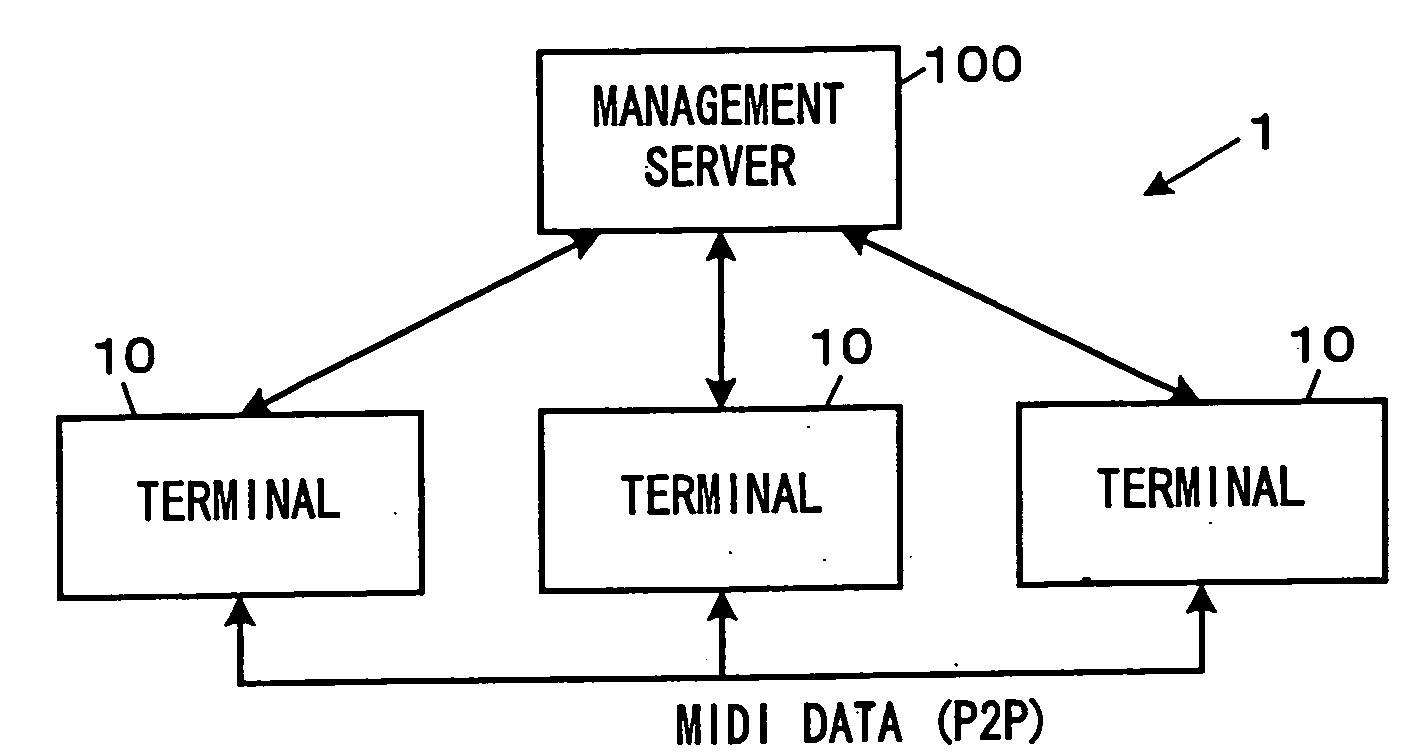
[0043] First, a first embodiment of a communication management system for performance data will be described. FIG. 1 is a block diagram showing a schematic configuration of the communication management system for performance data.

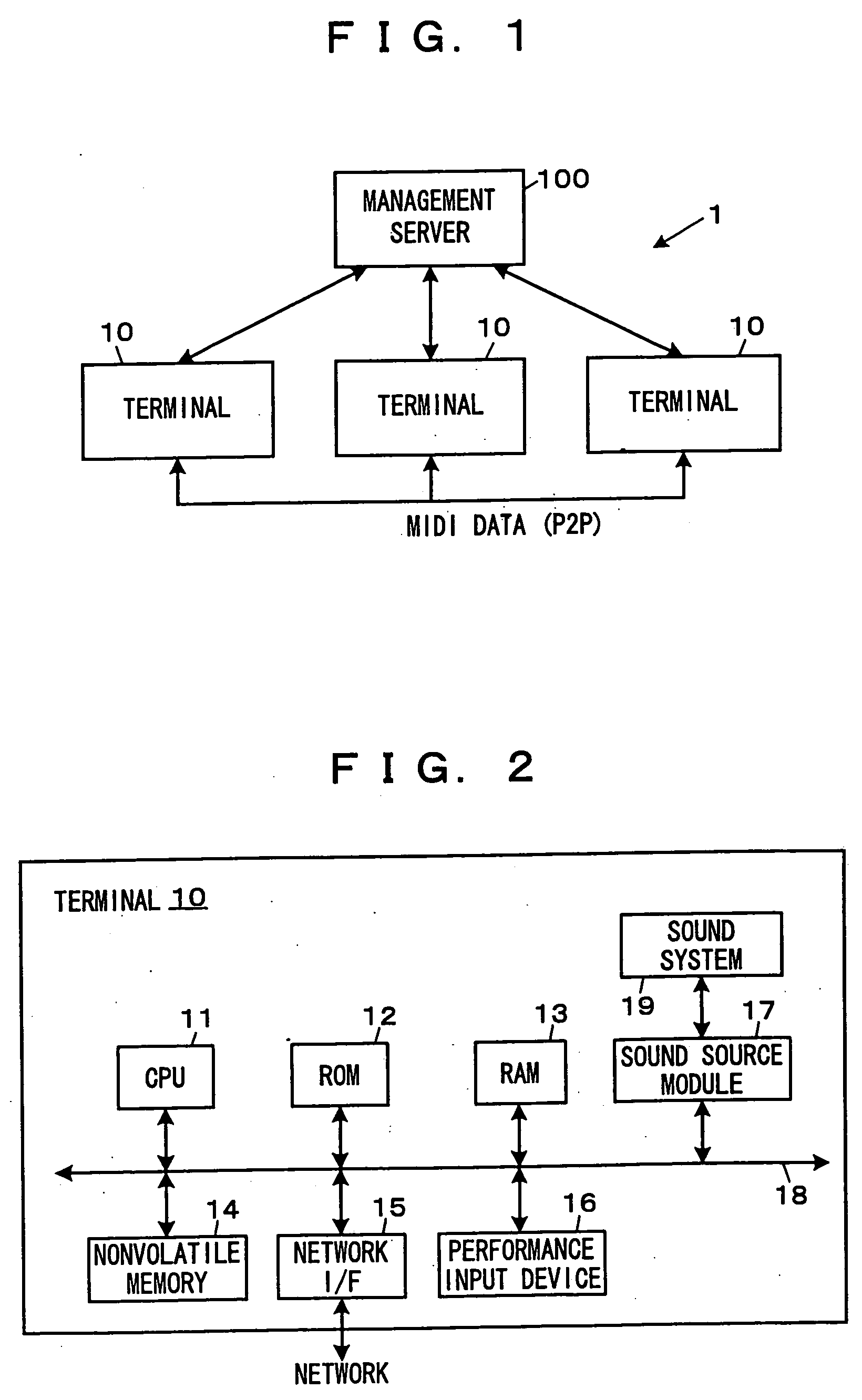
[0044] A communication management system 1 for performance data shown in FIG. 1 includes a management server 100 that manages a session for the transmission / reception of MIDI data being performance data when a plurality of terminals 10 transmit / receive the MIDI data to / from one another. Each of the terminals 10 corresponds to an electronic musical apparatus and the management server 100 corresponds to a communication management device for performance data.

[0045] The session here means that the plural terminals 10 transmit / receive (mutually exchange) MIDI data to / from communication partners in a specific group. By transmitting a request to the management server 100, each of the terminals 10 becomes a member of the group to join the session so that i...

second embodiment

FIG. 27

[0156] Next, a second embodiment of the communication management system for performance data will be described. FIG. 19 is a block diagram showing a schematic configuration of the communication management system for performance data.

[0157] In the communication management system 2 for performance data shown in FIG. 19, a plurality of terminals 20 are capable of communicating with one another via a network 30 and each of the terminals 20 has the function of the terminal 10 and the function of the management server 100 which are described in the first embodiment. That is, each of the terminals 20 corresponds to both an electronic musical apparatus and a communication management device for performance data. Note that one of the terminals 20 serves as a master node in a session of one group, and the function as the management server 100 is effective only in the master node and the function as the management server 100 is invalid in the other terminals 20.

[0158] Incidentally, if ...


PUM


Abstract

For performing a session in which performance data are mutually exchanged with other terminals via a communication network, a terminal searches for a master device managing the session, and when the master device is found, transmits a join notification to the master device to receive a notification of an allocated channel in response and also stores identification data notified from the master device. When the master device is not found, the terminal itself functions as the master device to allocate a channel in response to a join notification and to notify information on the terminals joining the session.

Description

BACKGROUND OF THE INVENTION [0001] 1. Field of the Invention [0002] The invention relates to an electronic musical apparatus having a function of performing a session in which performance data are mutually exchanged with other electronic musical apparatuses via a communication network. [0003] 2. Description of the Related Art [0004] Conventionally, there has been an art to connect, by cables, a plurality of devices dealing with performance data such as MIDI (Musical Instruments Digital Interface) data showing performance contents of a musical composition and allow these devices to transmit / receive the performance data to / from one another and cooperatively operate. [0005] For example, for transferring the MIDI data, dedicated interfaces and cables have been conventionally used. However, in recent years, proposed is an art to transfer a MIDI message through other communication protocol, thereby realizing the transfer of a larger volume of data to a more distant place than in the conve...

Claims


Application Information

Patent Timeline
Patent Type & Authority Applications(United States)
IPC IPC(8): G06F15/16
CPCG10H1/0058G10H2240/175G10H2240/305
Inventor UMEZAWA, SATORUMIYABE, MOTOAKI
Owner YAMAHA CORP
Why Eureka
Try Eureka