Packet trace diagnostic system

Inactive Publication Date: 2006-09-28
AGILENT TECH INC
View PDF7 Cites 47 Cited by
  • Summary
  • Abstract
  • Description
  • Claims
  • Application Information

AI Technical Summary

Benefits of technology

[0009] Accordingly, in a first aspect, the invention provides a packet trace diagnostic system for monitoring and displaying packet transfers in a telecommunications network, the packet trace diagnostic system comprising a control module for determining a packet trace to be monitored, the packet trace comprising a communications path between at least two communicating entities, the control module storing data packet transfer parameters relating to the determined packet trace, at least one monitoring module for monitoring data packets being transmitted along the communications path between the two communicating entities, a comparator module coupled to the monitoring module and the control mod

Problems solved by technology

The departure and arrival times may vary and the transmission time and receipt time are not necessarily appropriate criteria in these circumstances for determining similar packet traces.
A time delay between timing points may be caused by delays associated with transmitting packets between communicating entities, or processing delays at communicating

Method used


Image

  • Packet trace diagnostic system
  • Packet trace diagnostic system
  • Packet trace diagnostic system

Examples


Embodiment Construction

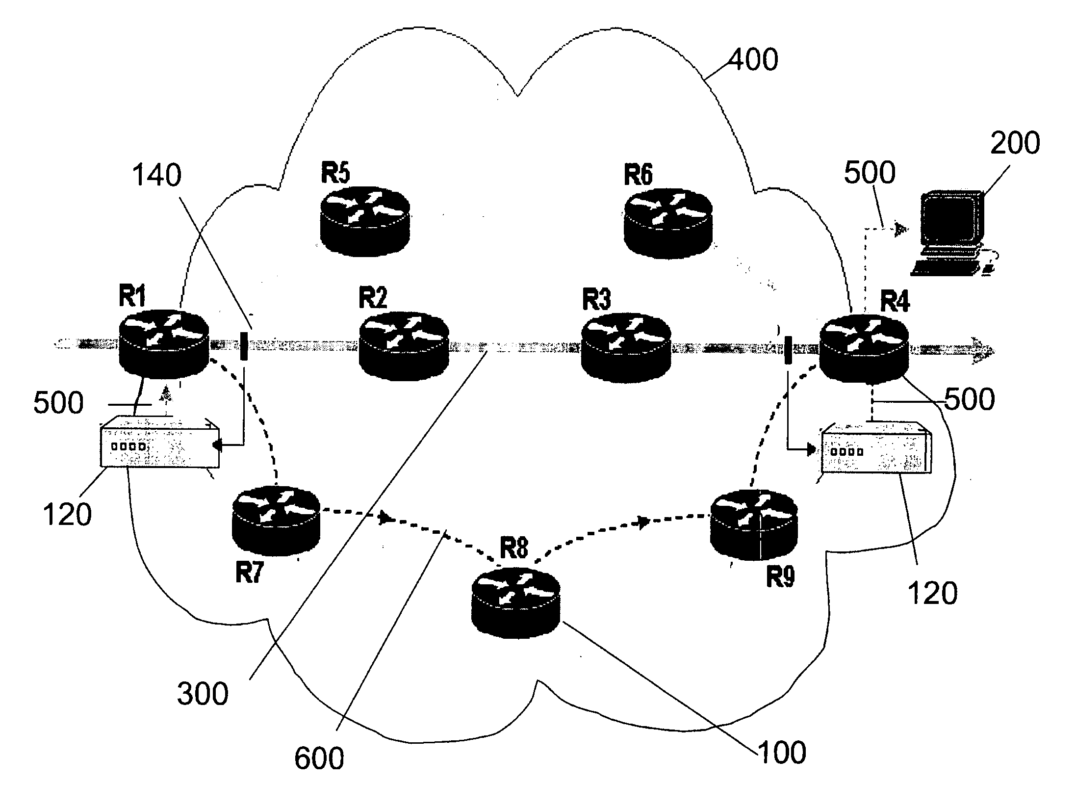
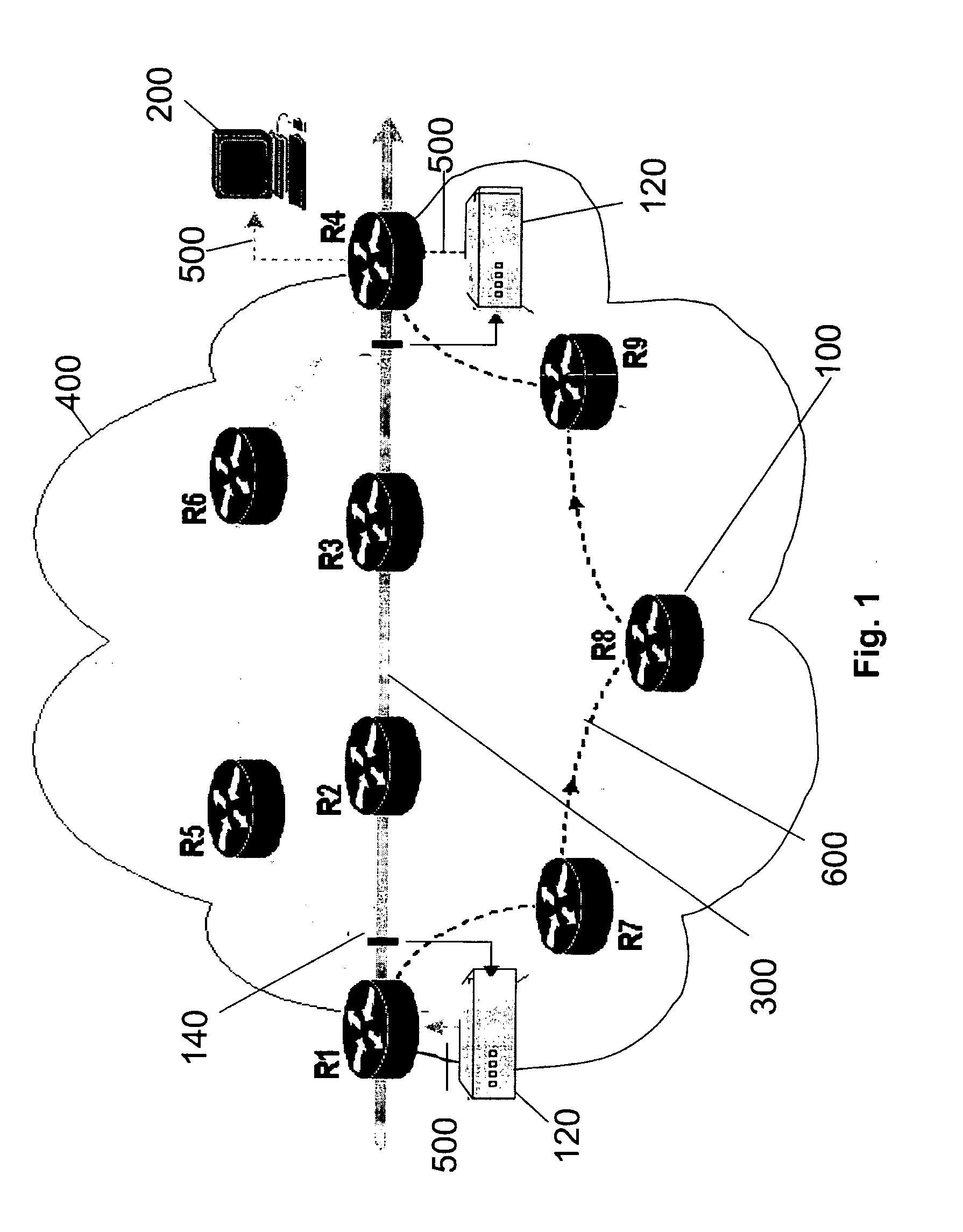
[0027] One embodiment of the present invention provides a packet trace diagnostic system. A schematic of a network 400 employing the packet trace diagnostic system is shown in FIG. 1. In this embodiment of the present invention the packet trace diagnostic system is implemented on one or more computers such as a Unix Solaris (of which only one is shown), which can also act as the network's management system 200 (NMS) and one or more monitoring probes 120, which are distributed across the network at particular points of interest for monitoring packets.

[0028] The network 400 comprises a series of Routers 100 labelled R1 to R7, each of which is connected by a series of communication paths 600. The network 400 also comprises a particular path of interest 300, which comprises a series of communication paths 600 connecting Routers R1, R2, R3 and R4. The path of interest 300 is monitored by the monitoring probes 120 (in this case two such probes) arranged to monitor particular points 140 i...


PUM


Abstract

A packet trace diagnostic system for monitoring and displaying packet transfers in a telecommunications network, especially so that faults or errors in the network can be detected quickly and easily, includes one or more monitoring probes for monitoring data packets being transmitted along selected communications path, a processor for predetermining acceptable data packet transfer characteristics, a measurement module for measuring data packet transfer characteristics and a comparator for comparing the measured data packet transfer characteristics to the predetermined acceptable packet transfer characteristics thereby enabling the identification of defective data packet transfers for the selected communications path. A user interface can be used to input acceptable packet transfer characteristics and a display may be used to display the results from the comparator on a message sequence chart, such as a ladder diagram. One of the packet transfer characteristics being measured may be packet transmission delay variation or “jitter”.

Description

BACKGROUND OF THE INVENTION [0001] The present invention relates to a packet trace diagnostic system for monitoring and displaying packet transfers in a telecommunications network, more specifically, for monitoring and displaying a plurality of packet transfers between the same endpoints in order for faults or errors in the network to be quickly and easily detectable. [0002] Some data communication networks, such as the Internet, employ packet switched technologies, where source data is split into packets. A packet can be defined by attributes such as, but not limited to, the departure time or creation time (from the transmitting entity), the arrival time (at the receiving entity), the source address of the packet, the destination address of the packet, the receiving entity (unique ID such as Media Access Control (MAC) address) and the packet type. [0003] Often in packet switched data communication networks, such as the Internet, there is no single dedicated connection between commu...

Claims


Application Information

Patent Timeline
IPC IPC(8): G06F11/00H04L12/26
CPCH04L43/0852H04L43/087H04L43/10H04L43/106
Inventor GARCIA, FRANCISCO JAVIERGARDNER, ROBERT
Owner AGILENT TECH INC
Why Eureka
Try Eureka