Wiper coupler and wiper assembly incorporating same

a wiper coupler and wiper assembly technology, applied in the field of windshield wiper assemblies, can solve the problems of generally more expensive tournament-style wiper assemblies, beam blade-style wiper assemblies, etc., and achieve the effects of simplifying the task associated, reducing costs, and reducing costs

Inactive Publication Date: 2006-10-05
TRICO PROD CORP
View PDF50 Cites 79 Cited by
  • Summary
  • Abstract
  • Description
  • Claims
  • Application Information

AI Technical Summary

Benefits of technology

[0012] Thus, one advantage of the present invention is that the wiper coupler operatively engages a tournament-style wiper assembly to a wiper arm originally adapted to operatively engage a beam blade-style wiper assembly.
[0013] Another advantage of the present invention is that the wiper coupler provides a tournament-style wiper assembly as a replacement option to beam blade-style wiper assemblies, thereby reducing costs associated with replacing a beam blade-style wiper assembly.
[0014] Still another advantage of the present invention is that it provides a wiper assembly system having a replaceable wiping element to reduce the costs associated with replacing a beam blade-style wiper blade assembly.
[0015] Yet another advantage of the present invention is that it provides a wiper assembly system incorporating a replaceable wiping element to be replaced by readily available wiping elements to simplify the task associated with replacing a beam blade-style wiper assembly.
[0016] Other objects, features and advantages of the present invention will be readily appreciated as the same becomes better understood after reading the subsequent description taken in connection with the accompanying drawings.

Problems solved by technology

While each style of wiper assembly has worked for its intended purpose, beam blade-style wiper assemblies are limited for use with a particular style of wiper arm, while tournament-style wiper assemblies may be employed in connection with a variety of wiper arm styles.
As a result of the limited aftermarket availability and fixed blade design, beam blade-style wiper assemblies are generally more expensive than tournament-style wiper assemblies.

Method used


Image

  • Wiper coupler and wiper assembly incorporating same
  • Wiper coupler and wiper assembly incorporating same
  • Wiper coupler and wiper assembly incorporating same

Examples


Embodiment Construction

)

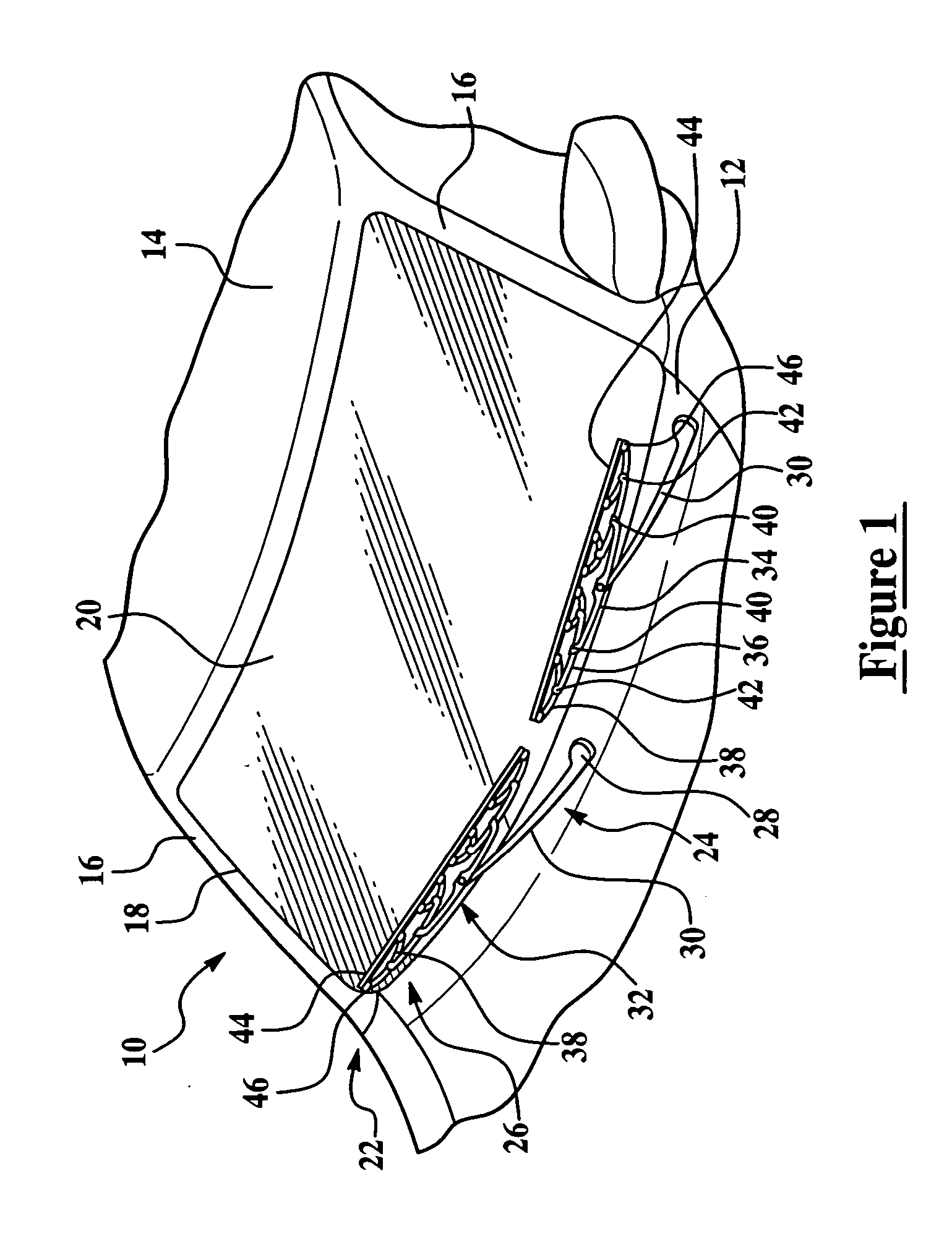
[0028] Referring now to the figures, where like numerals are used to designate like structure, a portion of a vehicle is schematically illustrated at 10 in FIG. 1. The vehicle includes a cowl 12, a roof 14, and a pair of laterally spaced front or “A” pillars 16 extending between the roof 14 and the cowl 12. The A-pillars 16, roof 14, and cowl 12 cooperate to define a generally rectangular opening 18 in which is supported a curved or “swept back” glass windshield 20.

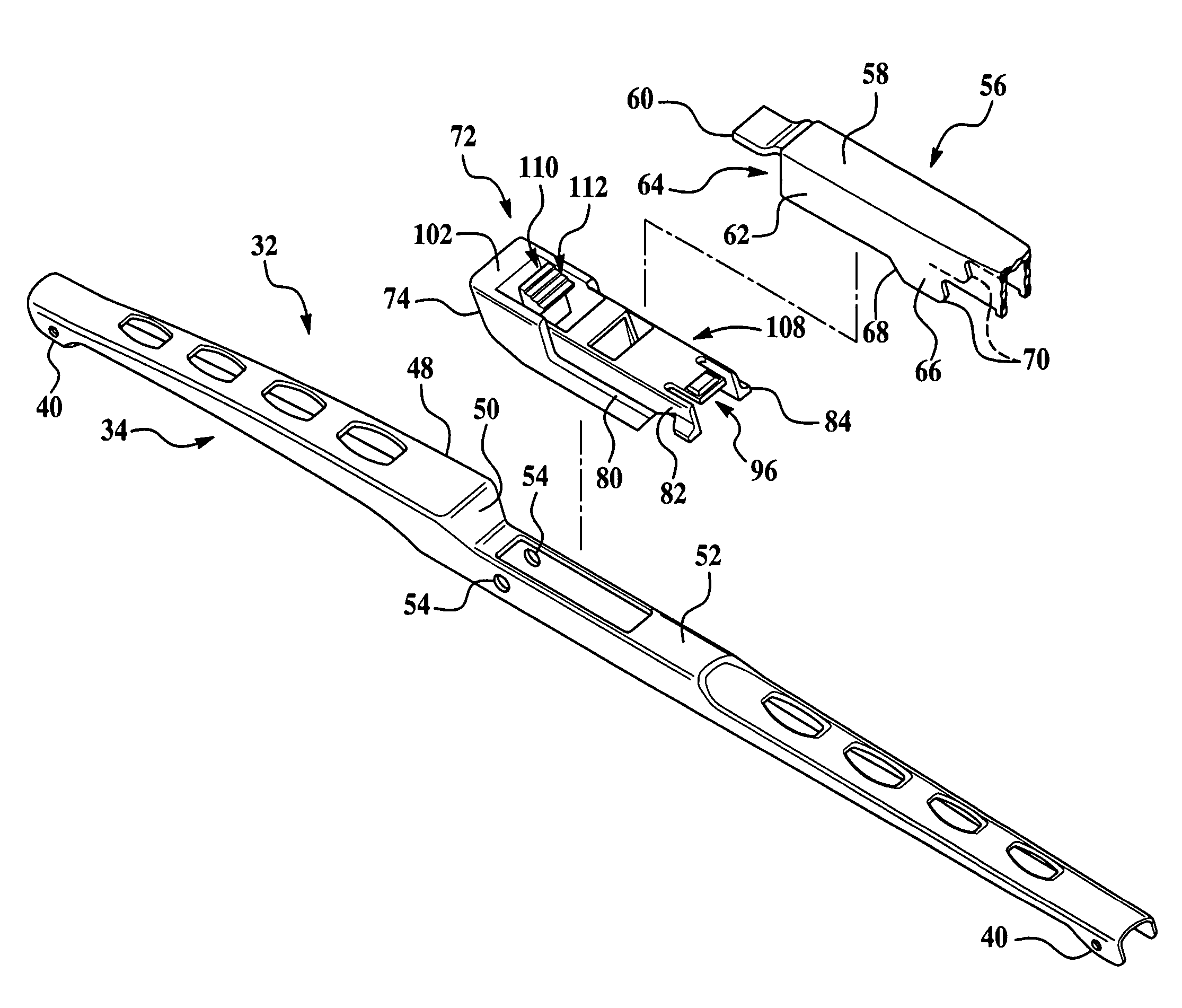
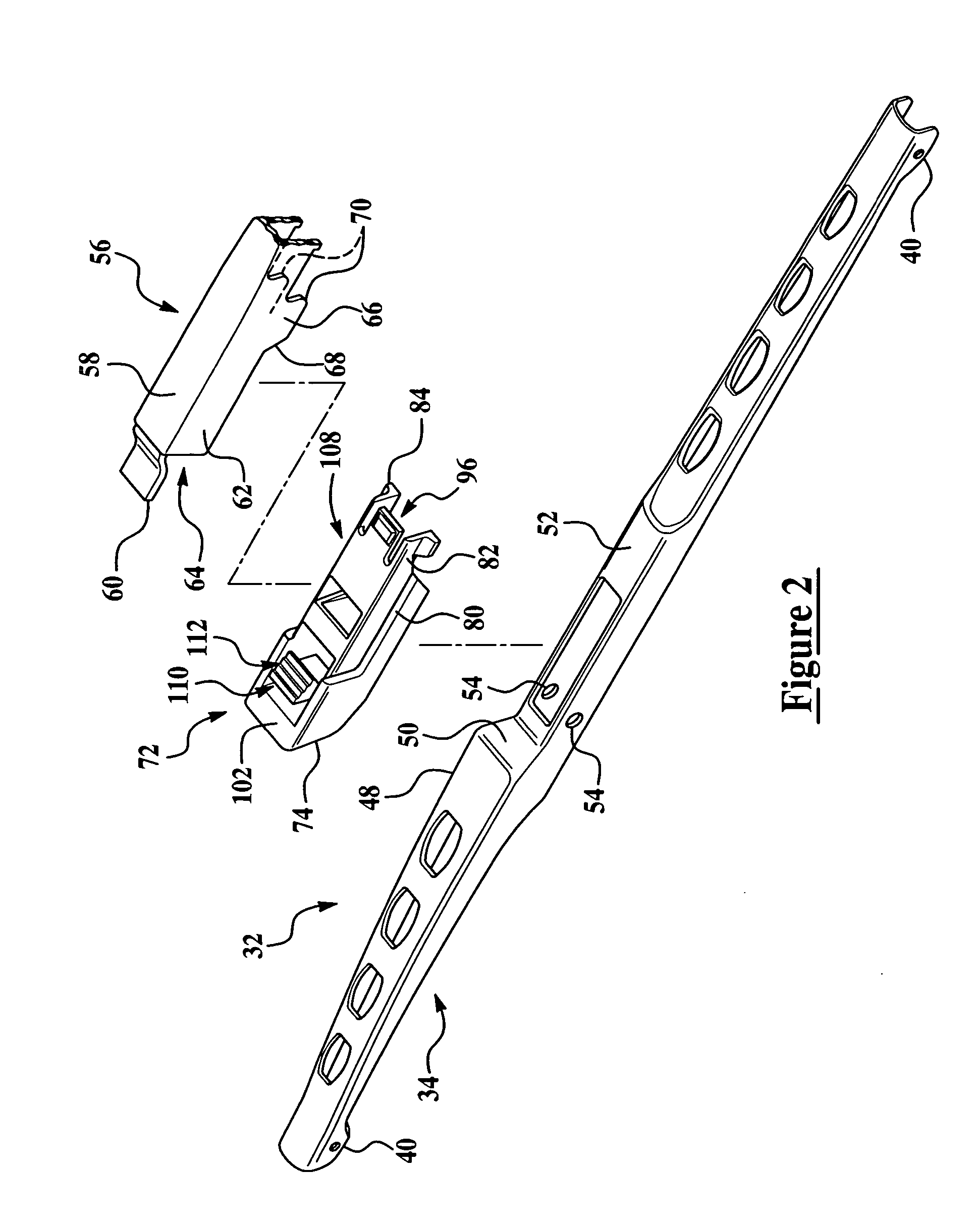
[0029] A wiper system is generally indicated at 22 in FIG. 1 and is employed to clean the glass windshield 20. The wiper system 22 includes a wiper arm, generally indicated at 24 and a wiper assembly, generally indicated at 26. Those having ordinary skill in the art will appreciate that a wiper system 22 may include more than one wiper arm 24 and more than one wiper assembly 26. By way of example and as indicated in FIG. 1, a wiper system 22 may include a pair of wiper arms 24 and wiper assemblies 26, which correspond t...


PUM


Abstract

The present invention relates to a wiper coupler and wiper assembly that includes a wiping element and a tournament-style superstructure to support the wiping element. The wiper assembly further includes a wiper coupler that releasably attaches the superstructure to a wiper arm attachment member. The wiper coupler includes a pair of sidewalls each having a flange to engage a portion of the guides of the attachment member and further includes an elevated platform and a deck each disposed between the sidewalls. The deck and a portion of the sidewalls define a rest to receive the track of the attachment member. The wiper coupler further includes an aperture between the elevated platform and the deck. The aperture receives a portion of the bent tab of the attachment member to facilitate attachment between the superstructure and the attachment member conventionally employed for use with a beam blade-style wiper assembly.

Description

CROSS-REFERENCE TO RELATED APPLICATION(S) [0001] This application claims benefit of U.S. Provisional Patent Application Ser. No. 60 / 668,025 entitled, “Wiper Coupler and Wiper Assembly Incorporating Same,” and filed on Apr. 4, 2005.BACKGROUND OF THE INVENTION [0002] 1. Field of the Invention [0003] The present invention relates, generally, to windshield wiper assemblies. More specifically, the present invention relates to a wiper coupler and windshield wiper assembly incorporating same for use in connecting the wiper assembly to the wiper arm of a vehicle. [0004] 2. Description of the Related Art [0005] Conventional windshield wiper assemblies known in the related art include some type of wiper assembly mounted to an arm which, in turn, is mounted adjacent the windshield and pivotally driven to impart reciprocating motion to the wiper assembly across the windshield. A rubber wiping element is supported by the wiper assembly and contacts the windshield across the surface to be wiped. ...

Claims


Application Information

Patent Timeline
Patent Type & Authority Applications(United States)
IPC IPC(8): B60S1/40
CPCB60S1/4038B60S2001/4054B60S2001/4051
Inventor COUGHLIN, TIMOTHY J.
Owner TRICO PROD CORP
Why Eureka
Try Eureka