Self stirring, heating and cooking assembly having interchangeable stirring devices

a technology of stirring device and stirring device, which is applied in the field of self stirring, heating and cooking assembly, can solve the problems of user waiting by the food for several hours, food may be burned or overcooked, and the need for repeated stirring is burdensome and inconvenient,

Inactive Publication Date: 2006-10-05
ROTO COOKWARE +1
View PDF21 Cites 50 Cited by
  • Summary
  • Abstract
  • Description
  • Claims
  • Application Information

AI Technical Summary

Benefits of technology

[0006] In particular, and by way of example only, one embodiment of the invention includes a self stirring cooking assembly including a container defined by a bottom surface and a side surface extending up from the bottom surface, a heating element for providing heat to the container, a stirring device having an arm positioned to rotate along the bottom surface of the container, the arm having a non-rectangular cross-section, and a motor configured to rotate the stirring device. The self stirring cooking assembly may have a base having a motor control for controlling the motor, where the motor is positioned in the base. The self stirring cooking assembly may also have a heating element coupled to the base or positioned within the container. For example, the heating element may be positioned inside or within the stirring device.

Problems solved by technology

The user must repeatedly stir the food in the container, otherwise, the food may be burned or overcooked.
Requiring the food to be repeatedly stirred is burdensome and inconvenient.
Moreover, if the food needs to be slow-cooked, the user may have to wait by the food for several hours.
For example, the automatic stirring devices are not capable of switching directions when blocked or stopped by the food or periodically for better stirring of the food.
Also, the automatic stirring devices do not have interchangeable stirring members for the stirring of different types of foods and the stirring members do not scrape the bottom and side surfaces of the pot.
Furthermore, the stirring devices are not specifically designed for heating and stirring certain types of foods.

Method used


Image

  • Self stirring, heating and cooking assembly having interchangeable stirring devices
  • Self stirring, heating and cooking assembly having interchangeable stirring devices
  • Self stirring, heating and cooking assembly having interchangeable stirring devices

Examples


Embodiment Construction

[0021] Devices and methods that implement the embodiments of the various features of the invention will now be described with reference to the drawings. The drawings and the associated descriptions are provided to illustrate embodiments of the invention and not to limit the scope of the invention. Reference in the specification to “one embodiment” or “an embodiment” is intended to indicate that a particular feature, structure, or characteristic described in connection with the embodiment is included in at least an embodiment of the invention. The appearances of the phrase “in one embodiment” in various places in the specification are not necessarily all referring to the same embodiment. Throughout the drawings, reference numbers are re-used to indicate correspondence between referenced elements. In addition, the first digit of each reference number indicates the figure in which the element first appears.

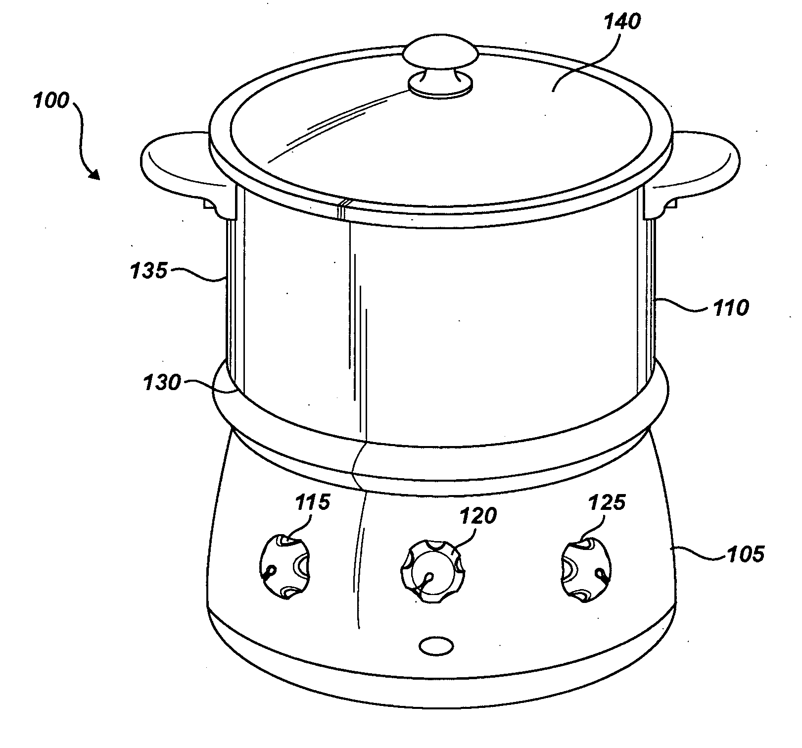
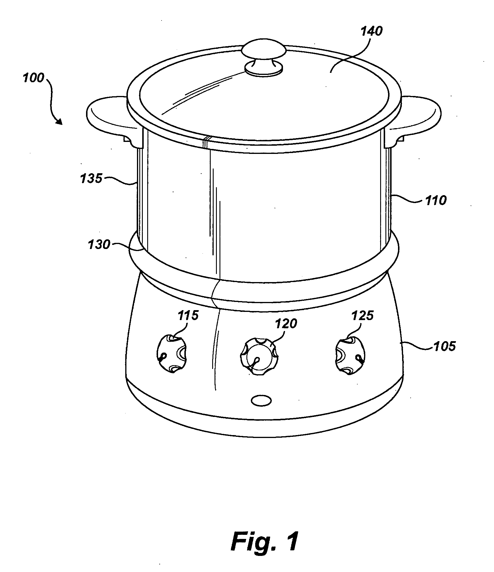
[0022] Referring now more particularly to the drawings, FIG. 1 is a perspective...


PUM


Abstract

A self stirring cooking assembly including a container defined by a bottom surface and a side surface extending up from the bottom surface, a stirring device having an arm positioned to rotate along the bottom surface of the container, the arm having a non-rectangular cross-section, and a motor configured to rotate the stirring device. The self stirring cooking assembly may have a base having a motor control for controlling the motor, where the motor is positioned in the base. The self stirring cooking assembly may also have a heating element coupled to the base or positioned within the container. That is, the heating element may be positioned on the base or within the stirring device.

Description

FIELD OF THE INVENTION [0001] The invention relates generally to a self stirring, heating and cooking assembly, and more particularly to a self stirring, heating and cooking assembly having interchangeable stirring devices. DESCRIPTION OF RELATED ART [0002] Containers (e.g., pots and pans) may be used to heat and / or cook food on conventional electric or gas stoves. After placing the container on the stove, a user generally turns on the stove, places the food in the container and stands by the stove to repeatedly stir the food. The user must repeatedly stir the food in the container, otherwise, the food may be burned or overcooked. Requiring the food to be repeatedly stirred is burdensome and inconvenient. Moreover, if the food needs to be slow-cooked, the user may have to wait by the food for several hours. [0003] To overcome the above drawbacks, several automatic stirring devices have been developed to stir food in a container. For example, U.S. Pat. No. 5,013,158 issued to Tarlow ...

Claims


Application Information

Patent Timeline
Patent Type & Authority Applications(United States)
IPC IPC(8): A21B7/00
CPCA47J43/046A47J27/004
Inventor GELFAND, JONATHAN
Owner ROTO COOKWARE
Why Eureka
Try Eureka