Microvalve having magnetic wax plug and flux control method using magnetic wax

a micro-valve and magnetic wax technology, applied in the direction of valve operation/release device, mechanical equipment, transportation and packaging, etc., can solve the problem of valve not being reused

Active Publication Date: 2006-10-05
PRECISIONBIOSENSOR INC
View PDF4 Cites 43 Cited by
  • Summary
  • Abstract
  • Description
  • Claims
  • Application Information

AI Technical Summary

Benefits of technology

[0014] According to an aspect of the present invention, a microvalve having a magnetic wax plug comprises a micro fluidic structure having an inlet portion and an outlet portion, a magnetic wax plug provided at a predetermined section where the inlet portion and the outlet portion meet, existing in a solid state, melted at a temperature higher than a predetermined temperature, and reversibly moving along a magnetic field, so as to control flux of a fluid through the micro fluidic structure, a heating portion provided corresponding to the section and heating the magnetic wax plug to be melted, and a magnetic field application portion selectively applying a magnetic field to a position where the melted magnetic wax plug arrives.
[0015] According to another aspect of the present invention, a microchip using a magnetic wax which performs a chemical reaction test with a small amount of a liquid test material using a micro fluidic structure formed on a substrate comprises a micro fluidic structure having a fine channel through which the liquid test material passes, and a magnetic wax member provided at a predetermined section of the micro fluidic structure, existing in a solid state, melted at a temperature higher

Problems solved by technology

However, since the mode change of the conventional phase change valve

Method used


Image

  • Microvalve having magnetic wax plug and flux control method using magnetic wax
  • Microvalve having magnetic wax plug and flux control method using magnetic wax
  • Microvalve having magnetic wax plug and flux control method using magnetic wax

Examples


Embodiment Construction

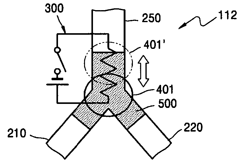
[0028] Throughout the accompanying drawings, the same reference numerals indicate the same elements having the same functions. FIG. 3 shows a microchip having a microvalve according to an embodiment of the present invention. Referring to FIG. 3, a microchip 110 has a predetermined micro fluidic structure formed in a substrate 200. The micro fluidic structure includes a plurality of microchannels and a microchamber 230. The microchannels include an inlet portion 210 having a test material input hole 211 at an end thereof, an outlet protion 220 connected to the microchamber 230, and a vent portion 250 which are connected together by a Y shaped or T-shaped connection portion. A magnetic wax member 500 is provided in the Y-shaped connection portion. A heating portion 300 capable of melting the magnetic wax member 500 by radiating heat is provided around the Y-shaped connection portion. The microchip 110 can be provided by itself or as a microchip unit including the microchip with a driv...


PUM


Abstract

Provided is a microvalve having a magnetic wax plug which includes a micro fluidic structure having an inlet portion and an outlet portion, a magnetic wax plug provided at a predetermined section where the inlet portion and the outlet portion meet, existing in a solid state, melted at a temperature higher than a predetermined temperature, and reversibly moving along a magnetic field, so as to control flux of a fluid through the micro fluidic structure, a heating portion provided corresponding to the section and heating the magnetic wax plug to be melted, and a magnetic field application portion selectively applying a magnetic field to a position where the melted magnetic wax plug arrives.

Description

CROSS-REFERENCE TO RELATED PATENT APPLICATIONS [0001] This application claims the benefit of Korean Patent Application No. 10-2005-0027829, filed on Apr. 2, 2005, in the Korean Intellectual Property Office, the disclosure of which is incorporated herein in its entirety by reference. BACKGROUND OF THE INVENTION [0002] 1. Field of the Invention [0003] The present invention relates to a microvalve and a microchip having a micro fluidic structure, and more particularly, to a bi-stable and phase change type microvalve provided in a micro fluidic structure and a microchip including the microvalve. [0004] 2. Description of the Related Art [0005] In general, a valve refers to an apparatus that is connected to a pipe to control the amount of flow or pressure of a fluid. A microvalve and other apparatuses comprising a microvalve related to a micro fluidic structure have received wide attention, particularly in a bio-chemical field including a micro total analysis system (μTAS). The microvalve...

Claims


Application Information

Patent Timeline
IPC IPC(8): F15C1/04
CPCF15C5/00F16K99/0001F16K99/0032F16K2099/0092F16K99/0046F16K2099/0084F16K2099/0086F16K99/0044Y10T137/2224Y10T137/2191Y10T137/0391Y10T137/4643Y10T137/2196B81B3/00
Inventor OH, KWANG-WOOKNAMKOONG, KAKPARK, CHIN-SUNG
Owner PRECISIONBIOSENSOR INC
Why Eureka
Try Eureka