

Oil pan with built-in filtering element
a filter element and oil pan technology, applied in the field of oil pans, can solve the problem that the filter element cannot be easily affected, and achieve the effect of reducing the number of parts, reducing the weight of the oil circulatory system, and reducing the weight of the oil pan
- Summary
- Abstract
- Description
- Claims
- Application Information
AI Technical Summary
Benefits of technology
Problems solved by technology
Method used
Image

Examples
first embodiment
[0071] First, a first embodiment will be explained.
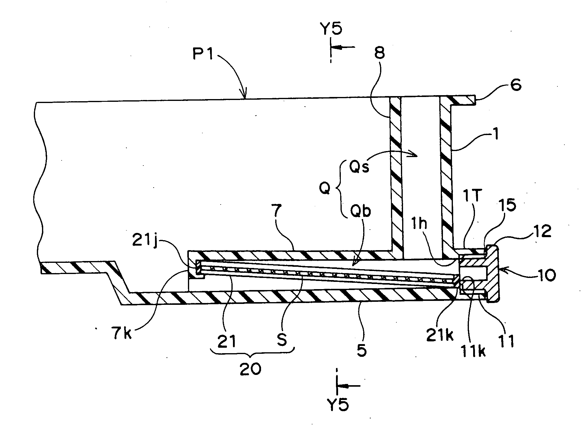
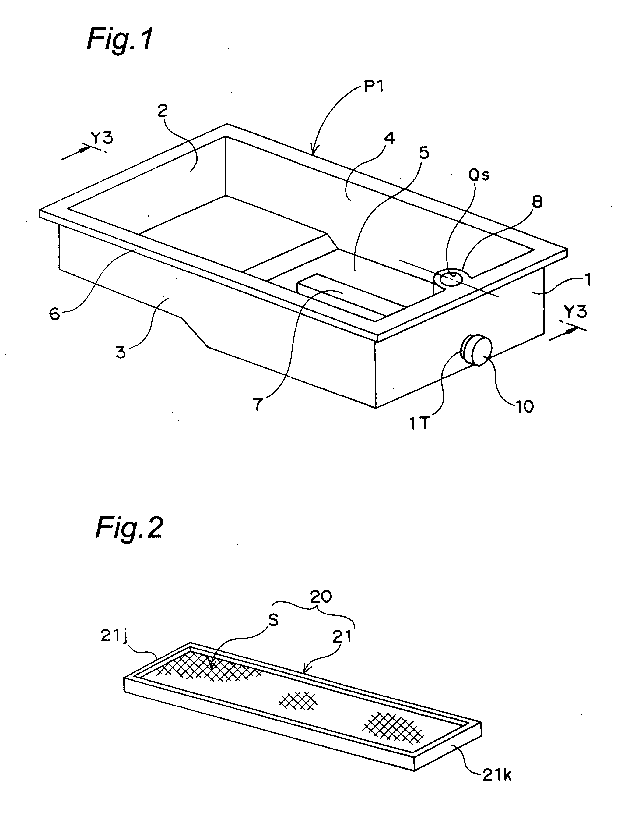
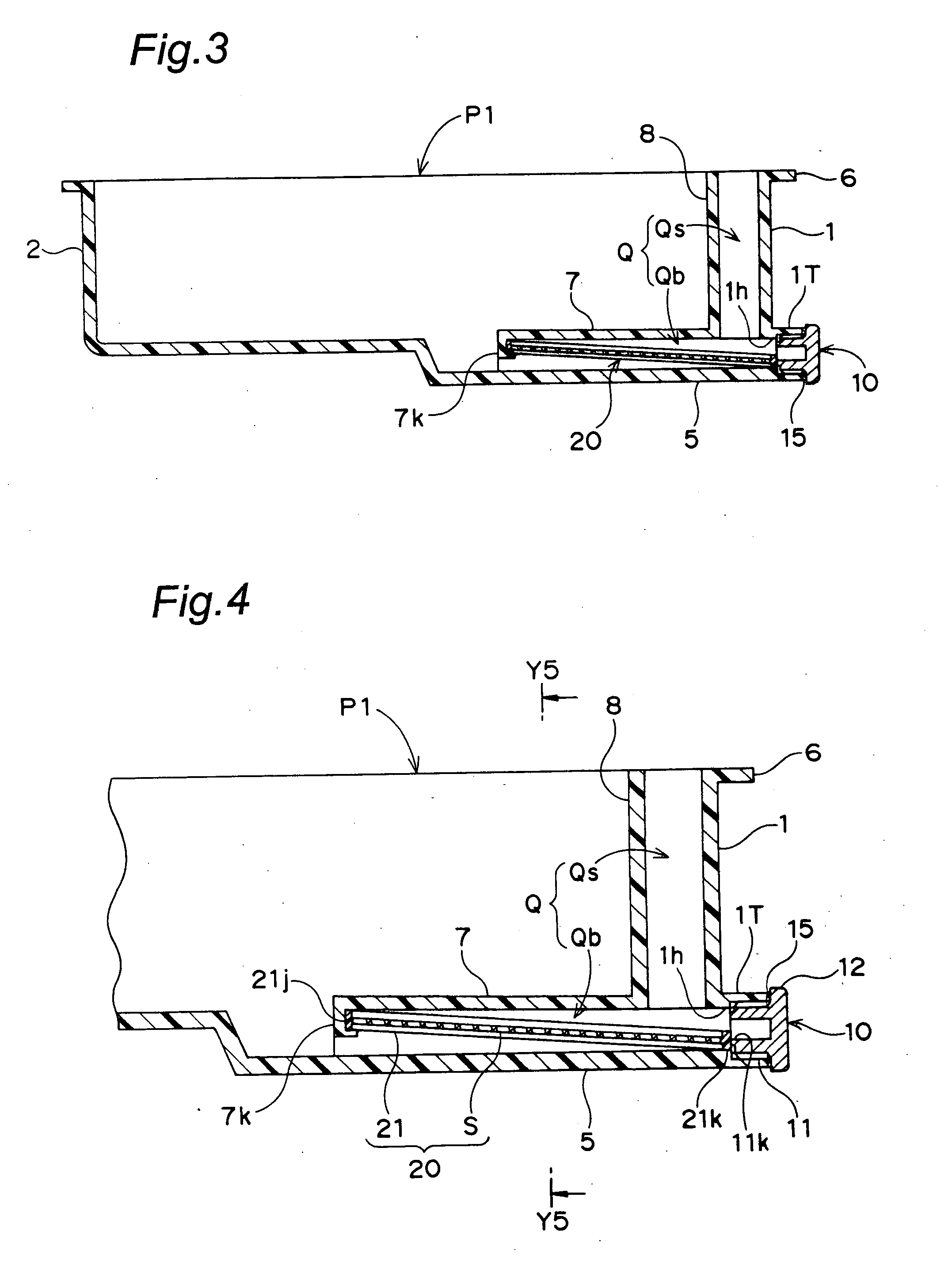
[0072]FIG. 1 is a perspective view showing an interior structure of an engine oil pan of an automobile according to a first embodiment of the present invention. FIG. 2 is a perspective view of an oil filter embedded in the oil pan. FIG. 3 is an explanatory sectional view of the oil pan taken along the line Y3-Y3 in FIG. 1. FIG. 4 is a partial explanatory sectional view of the oil pan in which an essential portion in FIG. 3 is enlarged. FIG. 5 is an explanatory sectional view of the oil pan taken along the line Y5-Y5 in FIG. 4. FIG. 6 is an enlarged explanatory sectional view of a fixed state of a closing plug of the oil pan
[0073] As can be seen in FIG. 1, an oil pan P1 according to the first embodiment is formed into a box-like shape which is opened upward. The oil pan P1 is of substantially rectangular shape as viewed from above. The oil pan P1 includes first and second sidewalls 1 and 2 which intersect with a longitudinal directi...
second embodiment
[0096] the invention will be explained with reference to FIGS. 7 to 10.
[0097] In the following explanation, elements of the second embodiment having the same structures and same effects as those of the first embodiment will be designated with the same symbols and further explanation thereof will be omitted.
[0098]FIG. 7 is a perspective view of an entire filter according to a second embodiment of the invention. FIG. 8 is an enlarged perspective view of an essential portion of the filter of the second embodiment. FIG. 9 is an explanatory sectional view of an essential portion of the oil pan according to the second embodiment which corresponds to FIG. 4. FIG. 10 is an explanatory sectional view of the oil pan taken along the line Y10-Y10 in FIG. 9.
[0099] According to a filter 30 of the second embodiment, frame portions of an upstream end 31j and a downstream end 31k of a frame 31 are the same as those of the first embodiment, but the filter 30 includes a pair of left and right vertic...
third embodiment
[0107] Next, the invention will be explained with reference to FIGS. 11 to 13.
[0108]FIG. 11 is a perspective view of an entire filter according to a third embodiment of the invention. FIG. 12 is an explanatory sectional view of an essential portion of the oil pan of the third embodiment corresponding to FIG. 4. FIG. 13 is an explanatory sectional view of the oil pan taken along the line Y13-Y13 in FIG. 12.
[0109] A filter 40 according to the third embodiment is similar to the filter 30 of the second embodiment, but the upstream end of each of vertical wall 42 of a frame 41 is not provided with a notch, and a filter retaining portion for retaining an upstream end 41j of the frame 41 is not provided on the upper inner side of the upstream end of the bottom flow path wall 7.
[0110] Instead, a convex portion 44 projecting downward by a predetermined amount is formed on a downstream end 41k of the frame 41 over its entire width. A step 5s with which the convex portion 44 of the frame 41 ...
PUM
| Property | Measurement | Unit |
|---|---|---|
| width | aaaaa | aaaaa |
| shape | aaaaa | aaaaa |
| area | aaaaa | aaaaa |
Abstract
Description
Claims
Application Information