
Ultra-broadband integrated balun

a balun and ultra-broadband technology, applied in the field of communication systems, can solve the problems of limiting the operational bandwidth of the spiral transformer, and the bandwidth limitations of the ring hybrid coupler

Active Publication Date: 2006-10-05
IBM CORP
View PDF5 Cites 19 Cited by
  • Summary
  • Abstract
  • Description
  • Claims
  • Application Information

AI Technical Summary

Benefits of technology

The patent describes a technology that allows for the transmission of signals using both millimeter waves and microwaves. The technology also includes the use of different types of capacitors to prevent the transmission lines from being affected by grounding. The overall effect of this technology is improved signal transmission at both high and low frequencies.

Problems solved by technology

The technical problem addressed in this patent relates to improving the performance of baluns in mm-wave, RF, and high-speed wired applications. Specifically, it discusses developing more efficient and compact baluns that can operate over wider ranges of frequencies without experiencing distortion or limited bandwidth. Additionally, it explores different ways to integrate baluns with other components while minimizing interference and reducing costs associated with manufacturing.

Method used


Image

  • Ultra-broadband integrated balun
  • Ultra-broadband integrated balun
  • Ultra-broadband integrated balun

Examples


Embodiment Construction

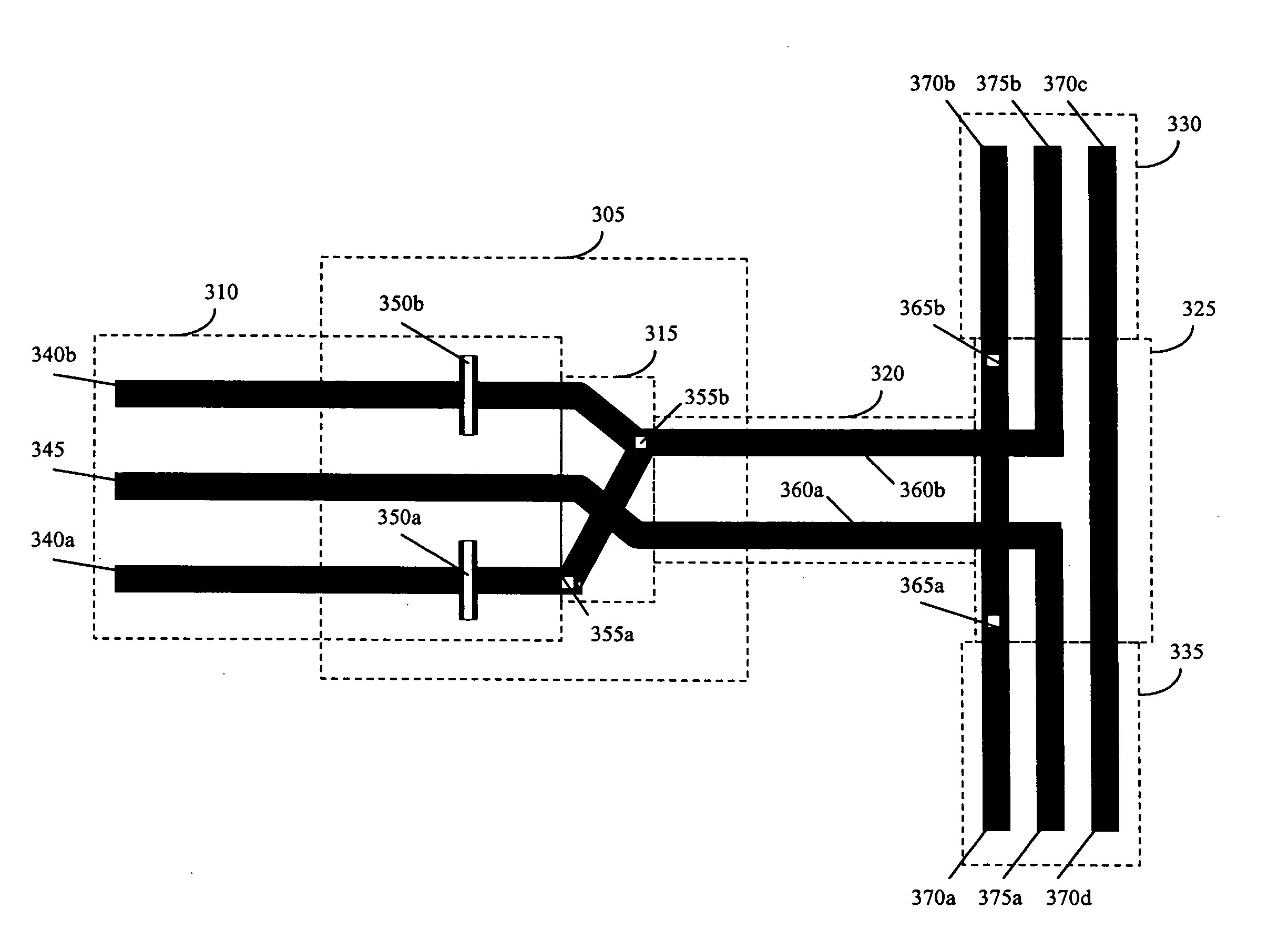
[0035]FIG. 3 is a diagram of an ultra-broadband balun structure according to an exemplary embodiment of the present invention. As shown in FIG. 3, an ultra-broadband balun 305 includes a portion of an unbalanced transmission line 310, a portion of a balanced transmission line 320 and a transition 315 between the unbalanced transmission line 310 and the balanced transmission line 320. The balun 305 also includes a pair of capacitors 350a,b connected to the unbalanced transmission line 310.

[0036] The unbalanced transmission line 310 includes a pair of ground traces 340a,b and a signal trace 345. The capacitors 350a,b are inserted in a portion of the ground traces 340a,b that are included in the balun 305. The balanced transmission line 320 includes a pair of signal traces 360a,b. One of the signal traces 360a is connected to the signal trace 345 and the other signal trace 360b is connected to the ground traces 340a,b through the transition 315 followed by the capacitors 350a,b. The t...


PUM


Abstract

An ultra-broadband balun is provided. The balun comprises: a first unbalanced transmission line comprising a first ground trace and a signal trace; and a balanced transmission line comprising a first and second signal trace, wherein the first signal trace of the balanced transmission line is connected to the first ground trace of the first unbalanced transmission line and the second signal trace of the balanced transmission line is connected to the signal trace of the first unbalanced transmission line, wherein a first capacitor is disposed in series with one of the first ground trace of the first unbalanced transmission line and the first signal trace of the balanced transmission line.

Description


Claims


Application Information

Patent Timeline
Owner IBM CORP
Learn More