Three-dimensional camcorder

a three-dimensional camcorder and camcorder technology, applied in the field of three-dimensional camcorder systems, can solve the problems of large device weight, huge cost, etc., and achieve the effect of improving image quality

Active Publication Date: 2006-10-05
STEREO DISPLAY
View PDF82 Cites 47 Cited by
  • Summary
  • Abstract
  • Description
  • Claims
  • Application Information

AI Technical Summary

Benefits of technology

[0027] To display three-dimensional video images in a volumetric display, the three-dimensional viewfinder comprises an image data input unit, a two-dimensional display, and a variable focal length MMAL. The image data input unit receives the depthwise image data or from the storage medium. The two-dimensional display, communicatively coupled to the image data input unit, displays depthwise images sequentially within the persistent rate of the human eyes. The variable focal length MMAL, optically coupled to the two-dimensional display, receives light from the two-dimensional display and forms a corresponding image at the required location in the space using the depth information of the depthwise image by changing the focal length of the MMAL. The image formed by the variable focal length MMAL is parallel to the three-dimensional viewfinder screen and located at the corresponding depth along the surface normal direction of the three-dimensional viewfinder screen. The location of the image formed in space is adjusted by changing the focal length of the variable focal length MMAL, which is synchronized with the two-dimensional display so that the variable focal length MMAL can have a focal length corresponding to the depth information of the depthwise image displayed in the two-dimensional display. As a set of depthwise images representing an object at a given moment are sequentially displayed in the two-dimensional display, a three-dimensional image of the object is formed in the space accordingly and perceived as three-dimensional by a viewer. The number of depthwise images representing the object at a given moment (number of depths) depends on the depth resolution requirement, the refresh rate of the two-dimensional display, and the focusing speed of the variable focal length MMAL, and may increase for a better image quality. A set of depthwise image representing an object at a given moment is displayed at least at the persistent rate of the human eye. The focusing speed of the variable focal length MMAL is at least equal to the product of the persistent rate of the human eye and the number of depths so that three-dimensional images formed in space looks realistic to the viewer.

Problems solved by technology

However, these devices tend to be large and heavy, and come at huge cost due to multiple camera systems and their optical axis separation requirement.

Method used


Image

  • Three-dimensional camcorder
  • Three-dimensional camcorder
  • Three-dimensional camcorder

Examples


Embodiment Construction

[0043] The present invention will now be described in detail with reference to a few embodiments thereof as illustrated in the accompanying drawings. In the following description, numerous specific details are set forth in order to provide a thorough understanding of the present invention. It will be apparent, however, to one skilled in the art, that the present invention may be practiced without some or all of these specific details. In other instances, well known process steps and / or structures have not been described in detail in order to not unnecessarily obscure the present invention.

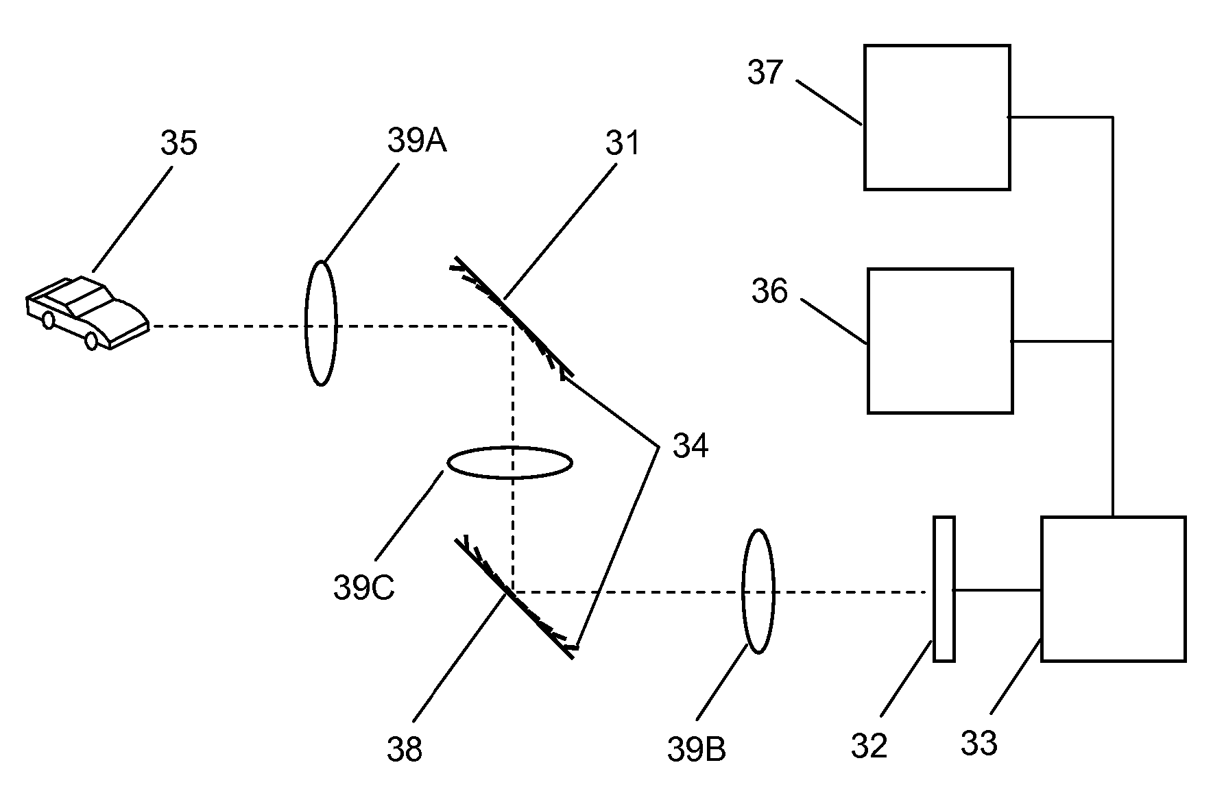
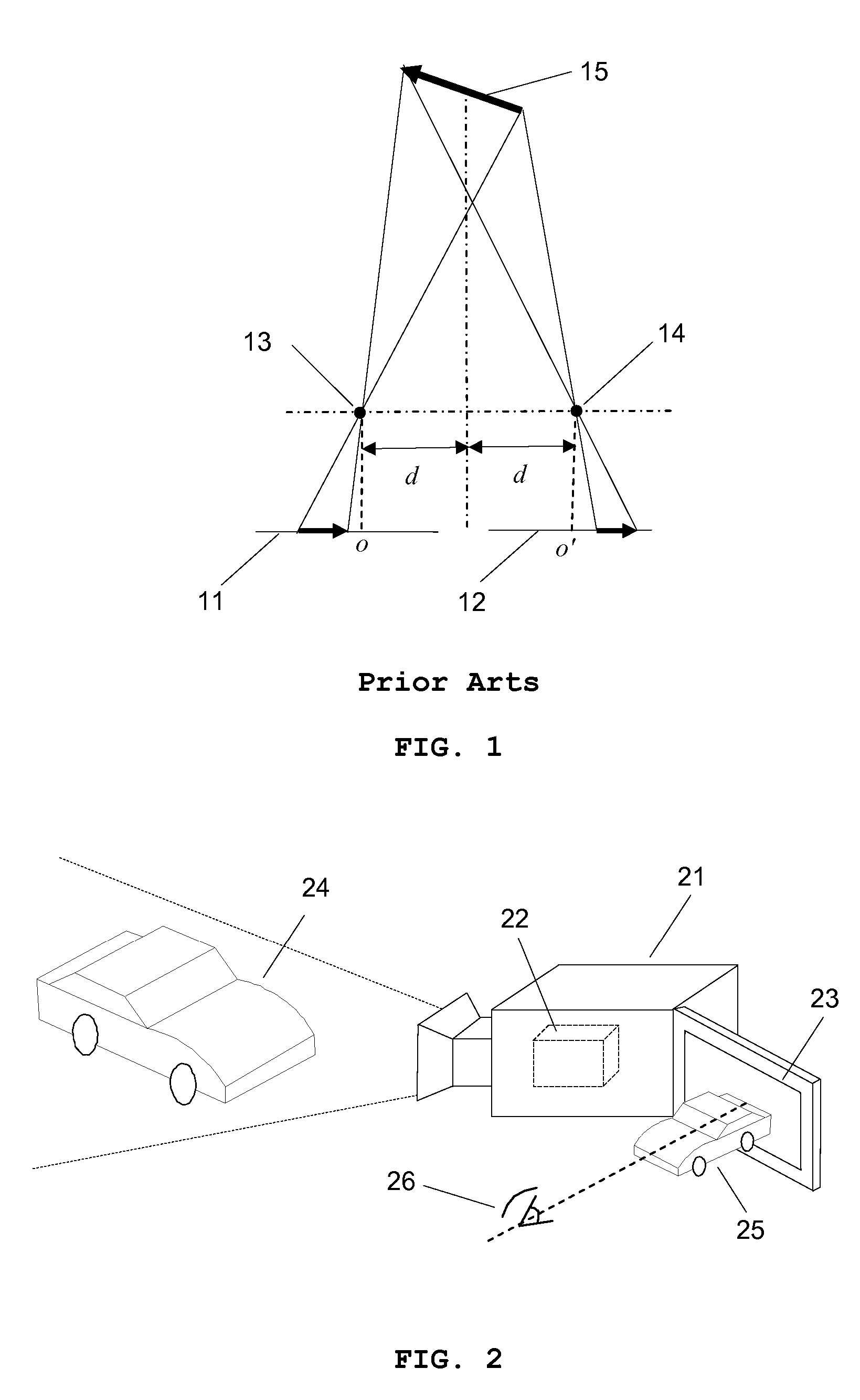
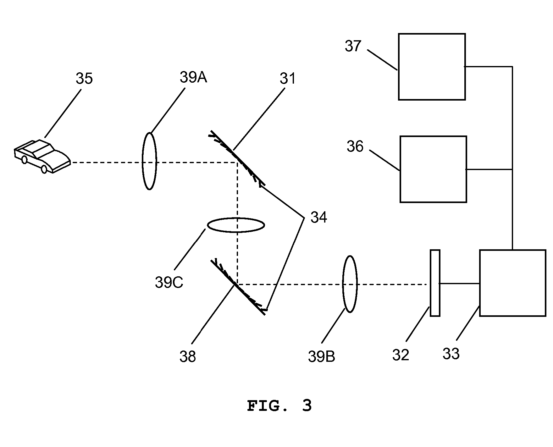
[0044]FIG. 2 illustrates a three-dimensional camcorder 21 comprising a three-dimensional imaging system 22 and a three-dimensional viewfinder 23. The three-dimensional imaging system 22 captures at least one image of an object 24 to provide depthwise images and the depth information for each depthwise image, as shown in FIG.3, one all-in-focus image and the depth information for each pixel of the ...


PUM


Abstract

The present invention provides a three-dimensional camcorder comprising a three-dimensional imaging system acquiring the three-dimensional image information of an object and a three-dimensional viewfinder displaying three-dimensional image using at least one variable focal length micromirror array lens.

Description

REFERENCE TO RELATED APPLICATIONS [0001] This application is a continuation-in-part of, and claims priority to U.S. patent application Ser. No. 10 / 822,414 filed Apr. 12, 2004, U.S. patent application Ser. No. 10 / 855,554 filed May 27, 2004, U.S. patent application Ser. No. 10 / 855,715 filed May 27, 2004, U.S. patent application Ser. No. 10 / 855,287 filed May 27, 2004, U.S. patent application Ser. No. 10 / 857,796 filed May 28, 2004, U.S. patent application Ser. No. 10 / 857,714 filed May 28, 2004, U.S. patent application Ser. No. 10 / 857,280 filed May 28, 2004, U.S. patent application Ser. No. 10 / 872,241 filed Jun. 18, 2004, U.S. patent application Ser. No. 10 / 893,039 filed Jul. 16, 2004, U.S. patent application Ser. No. 10 / 896,146 filed Jul. 21, 2004, U.S. patent application Ser. No. 10 / 979,612 filed Nov. 2, 2004, U.S. patent application Ser. No. 10 / 983,353 filed Nov. 8, 2004, U.S. patent application Ser. No. 11 / 072,597 filed Mar. 4, 2005, U.S. patent application Ser. No. 11 / 072,296 filed ...

Claims


Application Information

Patent Timeline
Patent Type & Authority Applications(United States)
IPC IPC(8): H04N13/02
CPCH04N13/0235H04N13/236
Inventor SEO, CHEONG SOOCHO, GYOUNG IL
Owner STEREO DISPLAY
Why Eureka
Try Eureka