Auto-focusing camera

Inactive Publication Date: 2006-10-05
INCHAN TECH
View PDF1 Cites 2 Cited by
  • Summary
  • Abstract
  • Description
  • Claims
  • Application Information

AI Technical Summary

Benefits of technology

[0008] The main objective of the invention is to prov

Problems solved by technology

To receive the digital camera with an increased thickness, the cellular phone must become t

Method used


Image

  • Auto-focusing camera
  • Auto-focusing camera
  • Auto-focusing camera

Examples


Embodiment Construction

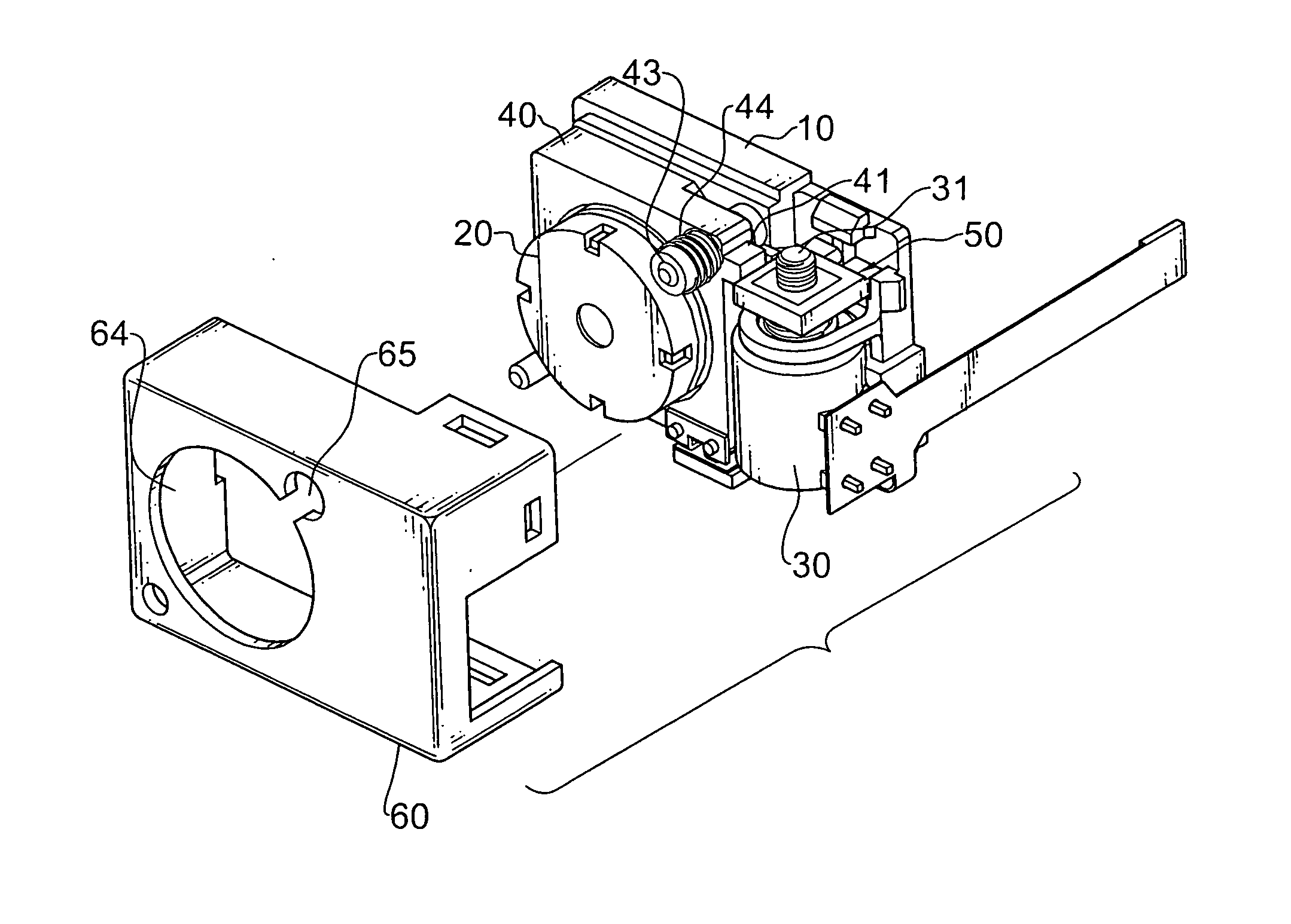
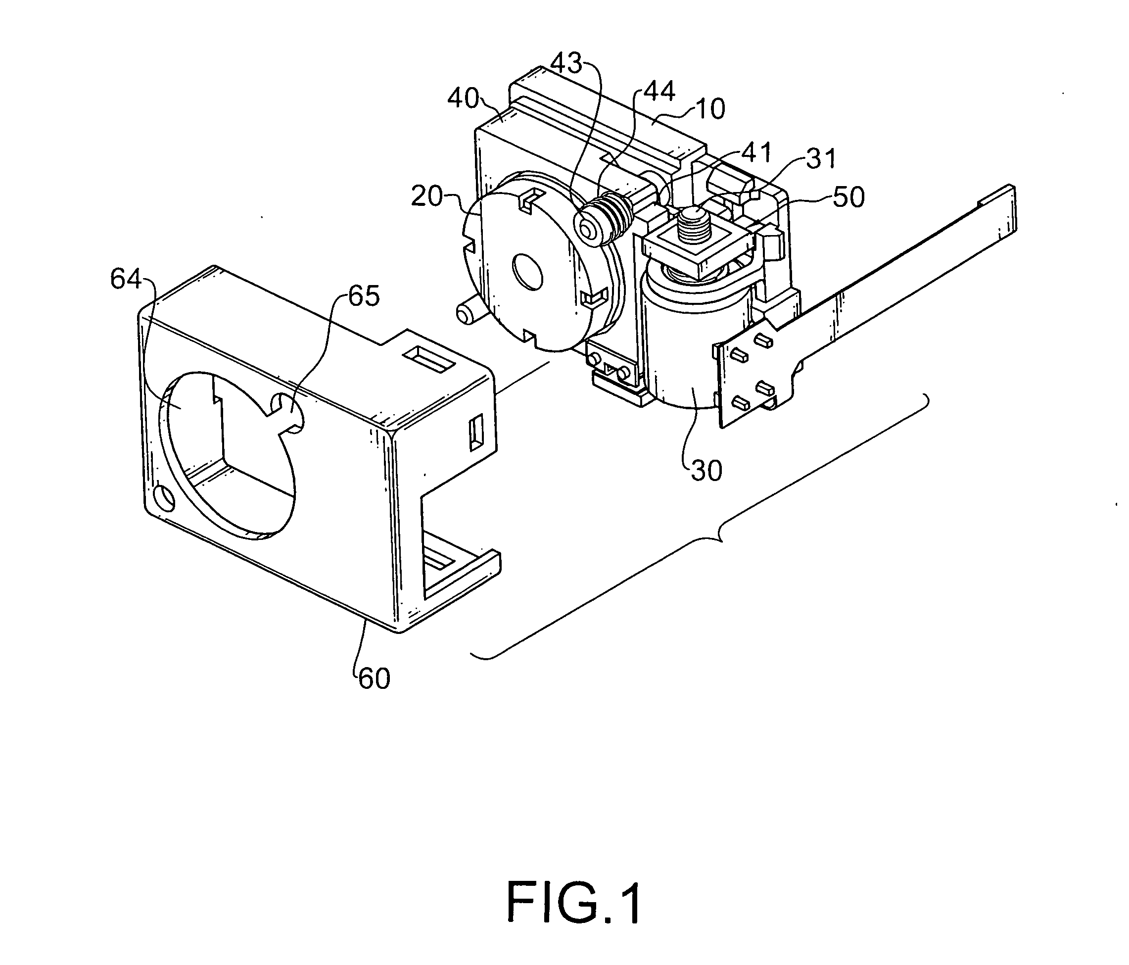
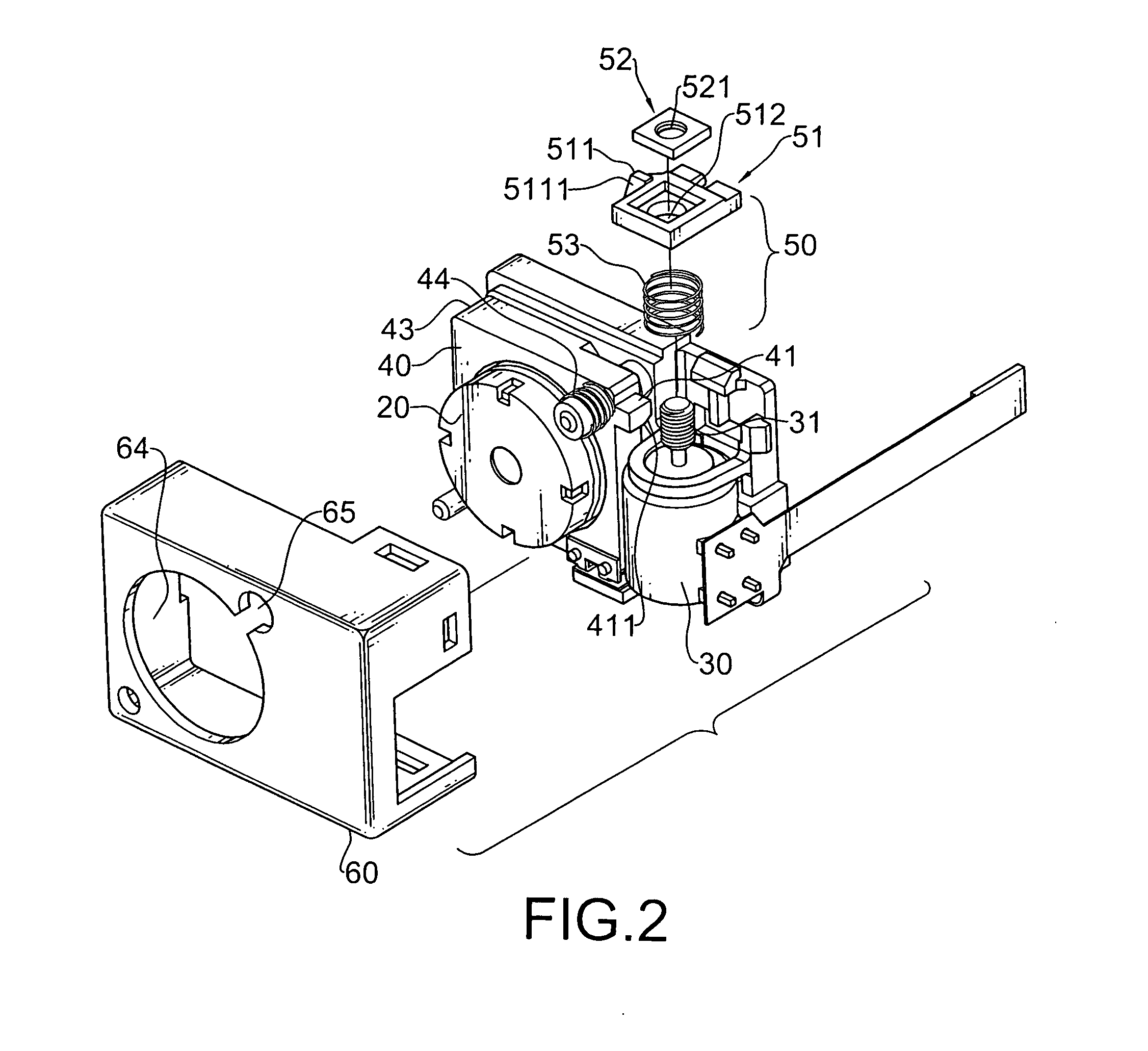
[0021] With reference to FIGS. 1 and 2, a auto-focusing camera in accordance with the present invention may be a digital camera, is mounted in an electrical appliance such as a cellular phone and comprises a base (10), a focusing element (40), a lens (20), a motor (30), a transmission assembly (50) and a cover (60).

[0022] The base (10) is mounted in the electrical appliance and has a front.

[0023] The focusing element (40) is mounted movably on the front of the base (10), can move away from or toward the base (10) and has a front, an outer edge, a driven element (41), a cylinder (43) and a spring (44). The driven element (41) is formed on the outer edge and has an inclined surface (411) relative to the front of the base (10). The cylinder (43) perpendicularly extends out the front of the focusing element (40). The spring (44) is mounted around the cylinder (43).

[0024] The lens (20) is mounted on the front of the focusing element (40) and has an axis perpendicular to the front of t...


PUM


Abstract

An auto-focusing camera has a base, a focusing element, a lens, a motor and a transmission assembly. The focusing element is mounted movably on the base. The lens is mounted on the focusing element. The motor is mounted and lies flatly on the base and has a shaft mounted rotatably to the motor. The transmission assembly connects to the shaft on the motor and the focusing element and allows the motor to move the focusing element through the transmission assembly. The motor lying on the base decreases a thickness of the auto-focusing camera along an axis of the lens and makes the auto-focusing camera thin and compact. The electrical appliance with the auto-focusing camera is thin, compact and salable.

Description

BACKGROUND OF THE INVENTION [0001] 1. Field of the Invention [0002] The present invention relates to a camera, and more particularly to an auto-focusing camera that is thin and compact. [0003] 2. Description of Related Art [0004] Cellular phones nowadays are designed to be compact with multiple functions to increase their marketability. One of popular functions of present cellular phones greatly increasing the marketability is photographing, which is implemented with a compact digital camera. [0005] With reference to FIG. 6, a conventional digital camera mounted in a cellular phone comprises a base (90), a motor (91), a focusing element (92), a lens (93), a connector (91) and a circuit board. The motor (91) is mounted upright on the base (90) and has an axis perpendicular to the base (90) and a threaded shaft (911) mounted rotatably on the motor (91). The focusing element (92) is mounted movably on the base (90). The lens (93) is mounted to the focusing element (92) and has an axis ...

Claims


Application Information

Patent Timeline
IPC IPC(8): G03B13/18G02B7/08G03B3/02G03B13/36G03B17/02H04N5/225H04N5/232
CPCG02B7/08G03B3/02H04N5/23212H04N5/2254H04N5/2257G03B17/02H04N23/57H04N23/55
Inventor YIN, TE-AN
Owner INCHAN TECH
Why Eureka
Try Eureka