Plane field type reflective liquid crystal display device having extraordinary polarizers

a liquid crystal display and field-type technology, applied in non-linear optics, instruments, optics, etc., can solve the problems of narrow viewing angle, inability to eliminate rlcd, and major contributor to power consumption of backlight, and achieve wide viewing angle, thin and compact

Inactive Publication Date: 2005-09-01
INNOLUX CORP
View PDF23 Cites 3 Cited by
  • Summary
  • Abstract
  • Description
  • Claims
  • Application Information

AI Technical Summary

Benefits of technology

[0011] Accordingly, an object of the present invention is to provide a liquid crystal display device which has a wide viewing angle, which can work at high temperatures, and which is relatively thin and compact.
[0012] Another object of the present invention is to provide a liquid crystal display device which achieves a good contrast ratio over wide viewing angles.
[0014] To achieve the second above-mentioned object, in three embodiments, the color filter layer is positioned above the upper polarizer. Optical beams reach the color filter layer after passing back through the liquid crystal layer and the upper polarizer. This arrangement reduces or eliminates the adverse effects of color filter de-polarizing, and yields a high contrast ratio over wide viewing angles.

Problems solved by technology

That is, the backlight is a major contributor to power consumption.
However, the RLCD still has an inherent drawback that cannot be eliminated; namely, a very narrow viewing angle.
However, the extra components increase costs proportionately.
In addition, because a polarizer used in the RLCD is made of PVA, it cannot work at temperatures higher than 80 degrees Centigrade.
This limits the kinds of application environments in which the RLCD can be used.
Furthermore, because the polarizer is positioned as an outer surface of the RLCD, it is easily damaged or even destroyed in handling or in use.
This makes the RLCD unduly thick and bulky.

Method used


Image

  • Plane field type reflective liquid crystal display device having extraordinary polarizers
  • Plane field type reflective liquid crystal display device having extraordinary polarizers
  • Plane field type reflective liquid crystal display device having extraordinary polarizers

Examples


Embodiment Construction

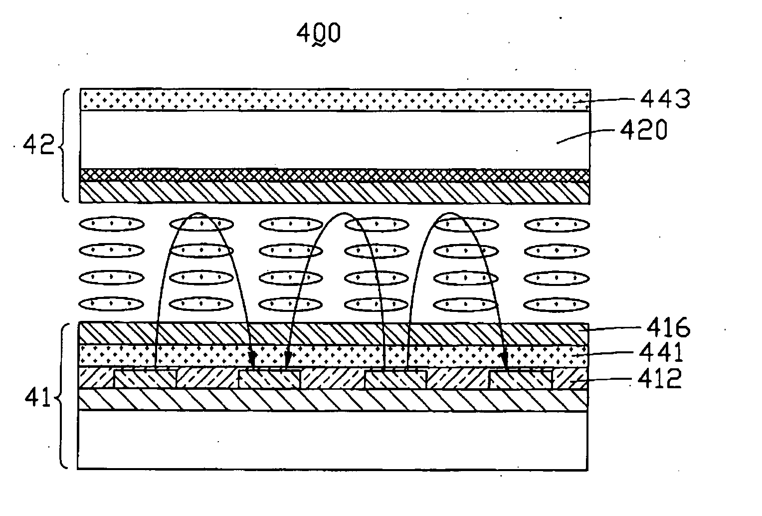
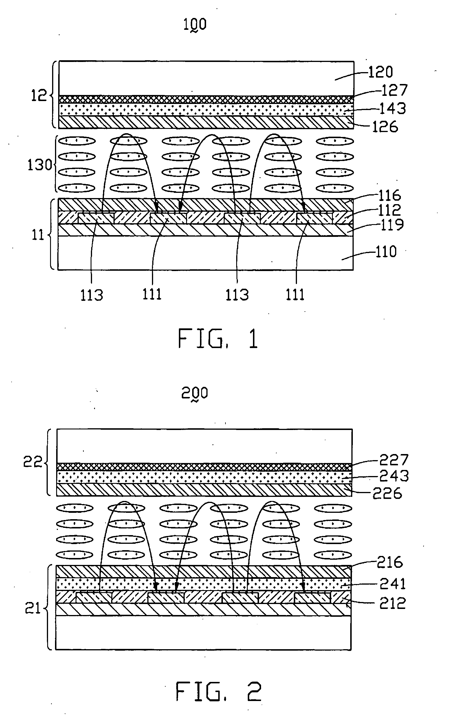
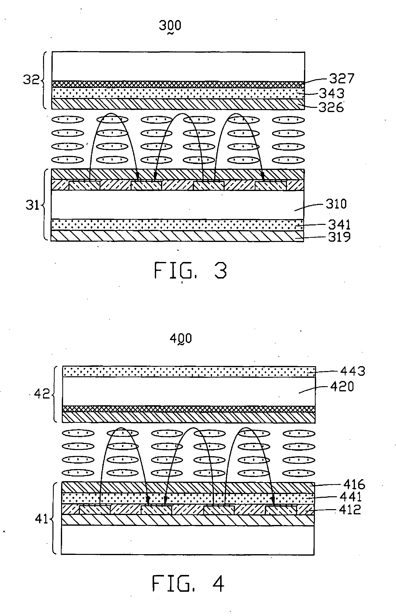
[0020] Referring to FIG. 1, a liquid crystal display device 100 of the first embodiment (“Example 1”) according to the present invention includes an upper substrate 12, a lower substrate 1, and a liquid crystal layer 130 interposed between the upper substrate 12 and the lower substrate 11. The upper substrate 12 comprises a color filter layer 127, an upper polarizer 143 and an upper alignment film 126 positioned in that order from top to bottom on an inner surface of an upper glass plate 120. The lower substrate 11 comprises a reflective film 119, a multiplicity of pairs of a pixel electrode 113 and a common electrode 111, an insulating layer 112 and a lower alignment film 116 positioned in that order from bottom to top on an inner surface of a lower glass plate 110. In an alternative embodiment, the upper glass plate 120 and the lower glass plate 110 can be made of silicon dioxide (SiO2) instead.

[0021] The pixel electrodes 113 and the common electrodes 111 are made of a transparen...


PUM

PropertyMeasurementUnit
thicknessaaaaaaaaaa
temperaturesaaaaaaaaaa

Abstract

A liquid crystal display device (100) includes an upper substrate (12), a lower substrate (11), and a liquid crystal layer (130) between the upper substrate and the lower substrate. The upper substrate includes an upper polarizer (143) and a color filter layer (127), the upper polarizer being an extraordinary type polarizer. The lower substrate includes a reflective film (119). A multiplicity of pixel electrodes (113) and common electrodes (111) are positioned at the lower substrate, for applying a voltage to the liquid crystal layer. The display device has a wide viewing angle, can work at high temperatures, and is relatively thin and compact. Further, the color filter layer is positioned above the upper polarizer. Optical beams reach the color filter layer after passing back through the liquid crystal layer and the upper polarizer. This reduces or eliminates color filter de-polarizing, and yields a high contrast ratio over wide viewing angles.

Description

CROSS REFERENCE TO RELATED APPLICATIONS [0001] This application is related to co-pending applications, two of which are entitled “In-plane field type transflective liquid crystal display device,” and one of which is entitled “Transflective liquid crystal display device,” and all of which are assigned to the same assignee as this application. BACKGROUND OF THE INVENTION [0002] 1. Field of the Invention [0003] The present invention relates to liquid crystal displays (LCDs), and more particularly to an in-plane field type reflective liquid crystal display device having at least one extraordinary type polarizer. [0004] 2. Description of the Prior Art [0005] Due to the features of being thin and consuming little power, liquid crystal display devices have been used in a broad range of fields. Applications include office automation (OA) apparatuses such as word processors and personal computers, portable information apparatuses such as portable electronic schedulers, videocassette recorder...

Claims


Application Information

Patent Timeline
Patent Type & Authority Applications(United States)
IPC IPC(8): G02F1/1335G02F1/1343
CPCG02F1/133528G02F2203/02G02F1/134363
Inventor YANG, CHIU-LIENCHEN, CHUEH-JUPANG, JIA-PANG
Owner INNOLUX CORP
Why Eureka
Try Eureka