

Esophageal balloon catheter with asymmetrical balloon
a balloon catheter and esophageal technology, applied in the field of medical devices, can solve problems such as difficult retraction
Inactive Publication Date: 2006-10-05
CORDIS CORP
View PDF9 Cites 15 Cited by
- Summary
- Abstract
- Description
- Claims
- Application Information
AI Technical Summary
Benefits of technology
"The present invention is about a medical device called a balloon catheter that can be used with an endoscope. The technical effect of this invention is that it provides a better way to use an endoscope for medical procedures."
Problems solved by technology
During such retraction into an endoscope or guiding catheter, the balloon material of some balloon catheters may possibly “bunch up” toward the distal direction as the balloon catheter is withdrawn back into such a passage or lumen, which may make retraction difficult.
Method used
View moreImage
Smart ImageViewing Examples

Examples
example
[0041] An example balloon catheter may be constructed, including a nylon balloon, nylon tubular outer body, a stainless steel inner member and a stainless steel wire embedded in the wall of the outer body. The wire may for example have a diameter of 0.2 mm, which can reduce elongation of the shaft to less than 1 mm per meter of catheter length, when a pull force of about 20 N is exerted.
Login to View More PUM
 Abstract
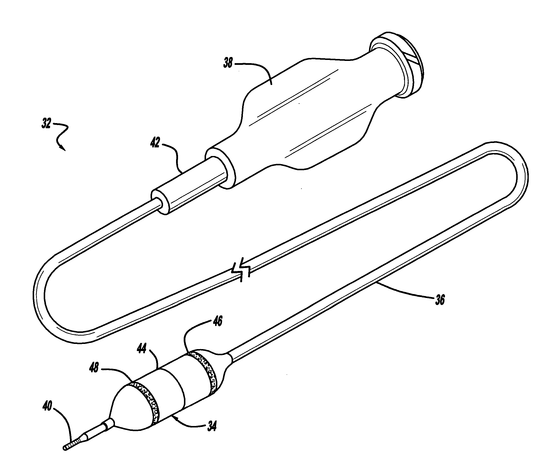
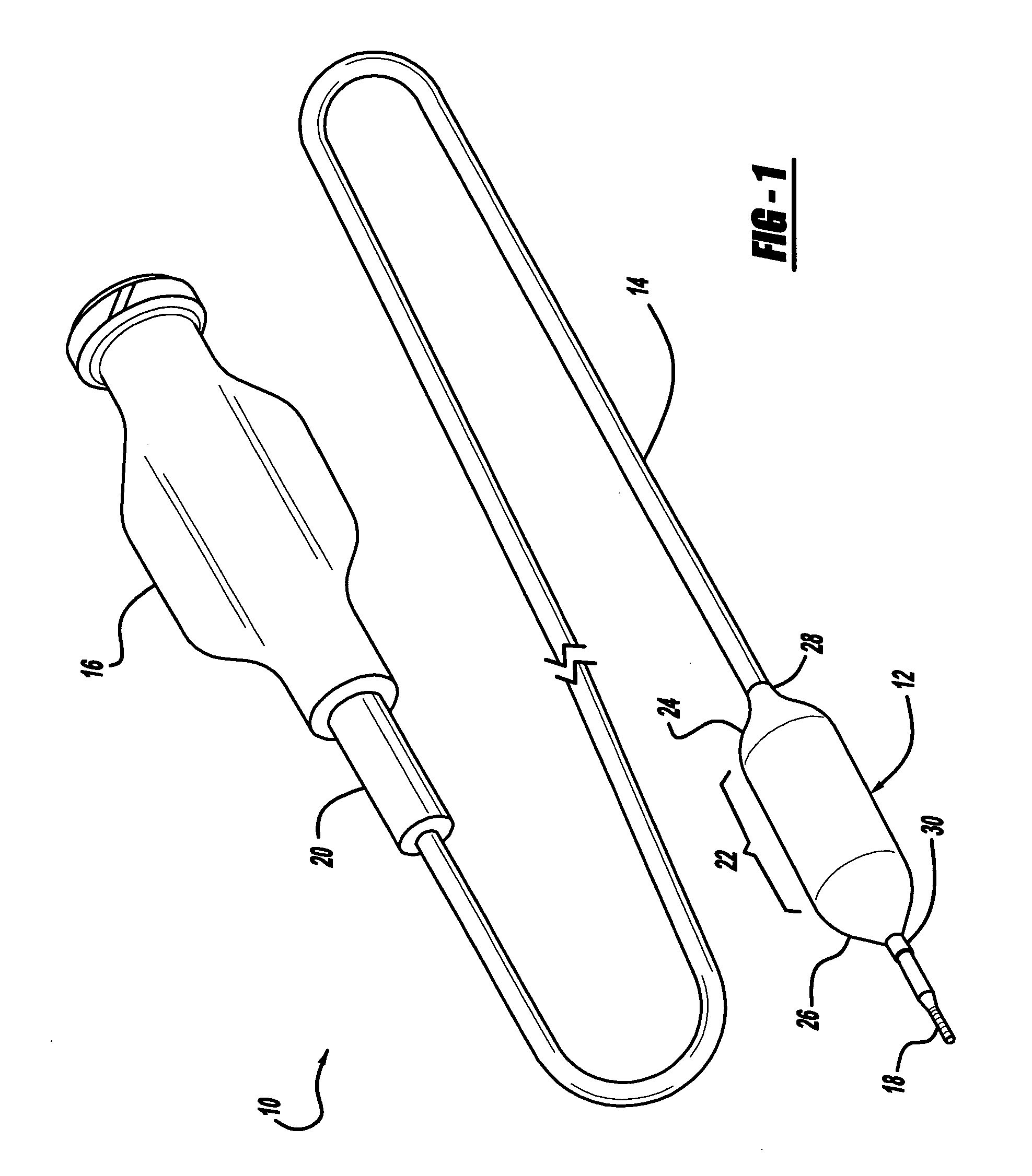
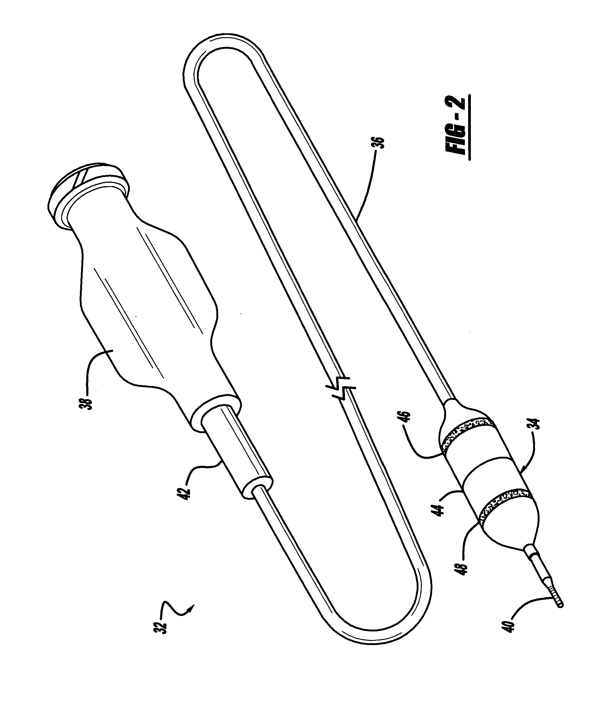
A balloon catheter for use with an endoscope may have a flexible shaft extending between a proximal and distal end, with a hub affixed to the proximal end, and a balloon that is longitudinally asymmetrical. A balloon may have a central or cylindrical working portion, flanked by proximal and distal tapering portions, which are in turn flanked by proximal and distal balloon legs, which are affixed to the catheter shaft. In more specific detail, a longitudinally asymmetrical balloon may have proximal and distal tapering portions that have a relatively steep and a relatively shallow tapering angle, respectively. An optional additional feature of such a balloon catheter is that the catheter shaft may have a high pull strength and low longitudinal elongation, by including some type of reinforcement.
Description
BACKGROUND AND SUMMARY OF THE INVENTION [0001] 1. Technical Background [0002] The present invention relates generally to medical devices, and more particularly to a balloon catheter for use with an endoscope. [0003] 2. Discussion [0004] There are many different kinds and types of balloon catheters, including for example angioplasty catheters, stent delivery system catheters, etc. [0005] By way of example, the present invention will be described in relation to an esophageal balloon catheter. However, it should be understood that the present invention relates to any balloon catheter having the features recited in any one of the following claims, and is not limited to any particular treatment such as esophageal use, or use with an endoscope, or the particular example embodiments described below. [0006] Balloon catheters often have a relatively flexible tubular shaft having a certain length, which defines one or more tubular passages or “lumens” extending through part or all of the cath...
Claims
Login to View More Application Information
Patent Timeline
 Patent Type & AuthorityApplications(United States)
IPC IPC(8): A61M29/00
CPCA61M25/0009A61M25/1002A61M2025/0098A61M2025/0008A61M25/1006
InventorVAN SLOTEN, LEONARD A.VAN WEE, COMELIUS
OwnerCORDIS CORP