Ultrasound catheter with embedded conductors

a technology of ultrasound catheter and conductor, which is applied in the field of catheters with ultrasound assemblies, can solve the problems of lack of flexibility necessary for navigation through difficult distal anatomy regions, inability to manufacture ultrasound catheters with a sufficiently small diameter for use in small vessels, and no existing ultrasound catheter is well adapted for effective use in small blood vessels in the distal anatomy. , to achieve the effect of increasing flexibility and maneuverability

Inactive Publication Date: 2006-10-05
WILSON RICHARD R +2
View PDF72 Cites 27 Cited by
  • Summary
  • Abstract
  • Description
  • Claims
  • Application Information

AI Technical Summary

Benefits of technology

[0009] In accordance with the foregoing, it is desired to provide an ultrasound catheter having increased flexibility and maneuverability. Such features are advantageous when a treatment is to be performed in the peripheral vasculature, and are especially advantageous when a treatment is to be performed in small vessels, such as in the neurovascular system.

Problems solved by technology

However, none of the existing ultrasound catheters is well adapted for effective use within small blood vessels in the distal anatomy.
For example, in one primary shortcoming, the region of the catheter on which the ultrasound assembly is located (typically along the distal end portion) is relatively rigid and therefore lacks the flexibility necessary for navigation through difficult regions of the distal anatomy.
Furthermore, it has been found that it is very difficult to manufacture an ultrasound catheter having a sufficiently small diameter for use in small vessels while providing adequate pushability and torqueability.
Still further, it has been found that the distal tip of an ultrasound catheter can easily damage the fragile vessels of the distal anatomy during advancement through the patient's vasculature.

Method used


Image

  • Ultrasound catheter with embedded conductors
  • Ultrasound catheter with embedded conductors
  • Ultrasound catheter with embedded conductors

Examples


Embodiment Construction

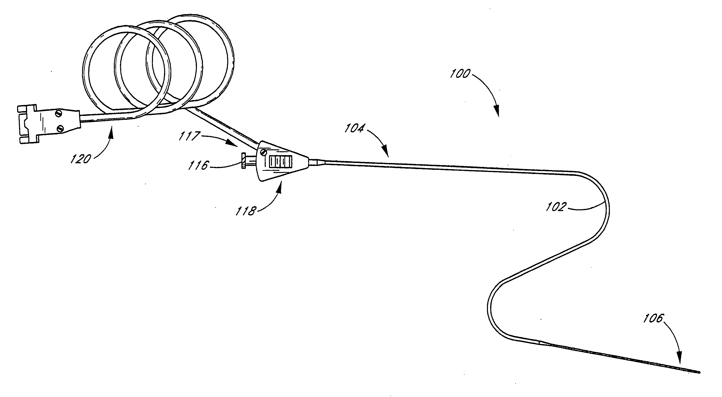
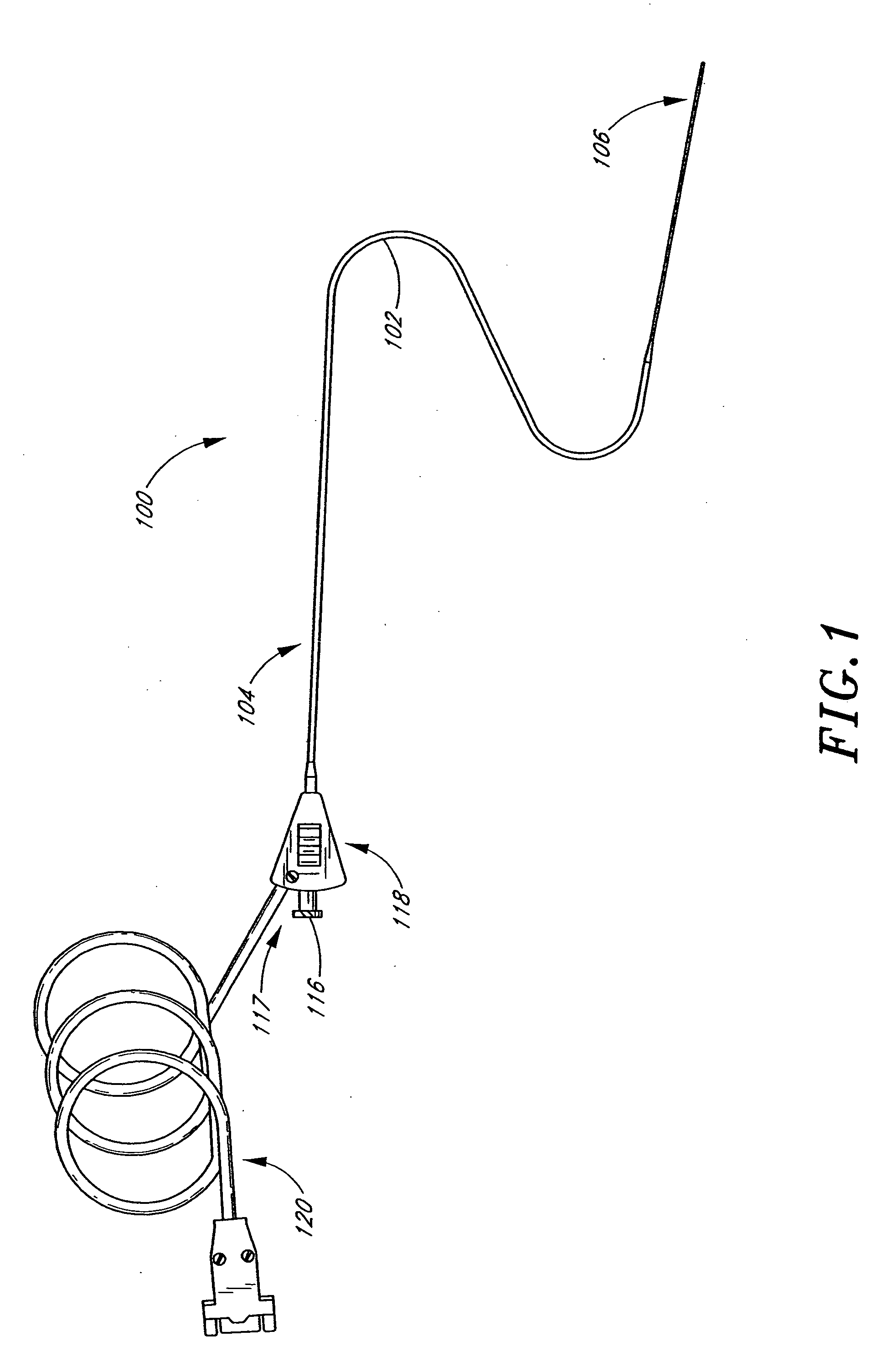
[0034] The advancement of an ultrasound catheter through a blood vessel to a treatment site can be difficult and dangerous, particularly when the treatment site is located within a small vessel in the distal region of a patient's vasculature. To reach the treatment site, it is often necessary to navigate a tortuous path around difficult bends and turns. During advancement through the vasculature, bending resistance along the distal end portion of the catheter can severely limit the ability of the catheter to make the necessary turns. Moreover, as the catheter is advanced, the distal tip of the catheter is often in contact with the inner wall of the blood vessel. The stiffness and rigidity of the distal tip of the catheter may lead to significant trauma or damage to the tissue along the inner wall of the blood vessel. As a result, advancement of an ultrasound catheter through small blood vessels can be extremely hazardous. Therefore, a need exists for an improved ultrasound catheter ...


PUM

PropertyMeasurementUnit
frequencyaaaaaaaaaa
frequencyaaaaaaaaaa
frequencyaaaaaaaaaa

Abstract

An ultrasound catheter comprises an elongate tubular body. The elongate tubular body has a proximal region and a distal region opposite the proximal region. The tubular body defines a central lumen having a central lumen diameter. The ultrasound catheter further comprises an elongate, hollow inner core extending through the central lumen. The elongate, hollow inner core has an inner core outer diameter that is less than or equal to the central lumen diameter. The ultrasound catheter further comprises an ultrasound radiating member positioned within the distal region of the tubular body and between the tubular body and the inner core. The ultrasound catheter further comprises at least two electrical conductors extending between the tubular body proximal region and the tubular body distal region. The at least two electrical conductors are positioned between the tubular body and the inner core. The at least two electrical conductors are electrically connected to the ultrasound radiating member. The at least two electrical conductors are wrapped around the inner core a plurality of times in a region between the ultrasound radiating member and the tubular body proximal region.

Description

PRIORITY INFORMATION [0001] This application is a divisional of U.S. patent Ser. No. 10 / 378,032, filed Feb. 28, 2003, which claims priority under 35 U.S.C. §119(e) from U.S. Provisional Patent Application Ser. No. 60 / 361,341, entitled “Small Vessel Catheter with Embedded Conductors” and filed Feb. 28, 2002 and is a continuation-in-part of U.S. patent application Ser. No. 10 / 309,417, entitled “Small Vessel Ultrasonic Catheter” and filed Dec. 3, 2002, the entire contents of these applications are hereby incorporated by reference.FIELD OF THE INVENTION [0002] The present invention relates to a catheter having an ultrasound assembly useful for delivering ultrasound energy at a treatment site in a body. The apparatus is particularly well suited for delivering ultrasound energy at a treatment site located within a small blood vessel in the distal anatomy. BACKGROUND OF THE INVENTION [0003] Several therapeutic and diagnostic applications use ultrasound energy. For example, ultrasound energ...

Claims


Application Information

Patent Timeline
Patent Type & Authority Applications(United States)
IPC IPC(8): A61M31/00A61N1/30A61B8/14A61B17/00A61B17/22A61M
CPCA61B17/22A61B17/2202A61B2017/00084A61B2017/22021A61B2017/22082Y10T29/49169B29C63/42Y10T29/49007Y10T29/49117Y10T29/49826A61B2017/22088A61B8/12
Inventor WILSON, RICHARD R.ABRAHAMSON, TIMOLIVER, LEONARD R.
Owner WILSON RICHARD R
Why Eureka
Try Eureka