Head support base unit with multi-directional capability

a technology of multi-directional capability and support base, which is applied in the field of base units, can solve the problems of occupying additional space, affecting the correct position affecting the efficiency of head holding components, so as to simplify the decision-making, the procedure, and/or the component

Active Publication Date: 2009-06-30
INTEGRA LIFESCI
View PDF14 Cites 10 Cited by
  • Summary
  • Abstract
  • Description
  • Claims
  • Application Information

AI Technical Summary

Benefits of technology

[0015]With rotatability along the longitudinal axis, the axis of a second clamp, located opposite the crossbar and a first clamp, may be selectively rotated to an orientation that is non-parallel with the connecting tube, and then locked in place at that selected orientation. In addition to this axial rotatability, this handle assembly still permits the conventional translational movement along the crossbar, rotational movement about the crossbar, and rotational movement at the second clamp. But with this additional degree of freedom, and hence this additional maneuverability, this base unit greatly enhances flexibility and maneuverability in locating and fixing a patient in a desired position relative to a medical table, without adding any additional knobs or securement devices, and without taking up more space.
[0018]For all of these reasons, the base unit of the present invention can be substituted for the prior conventional base unit to achieve numerous and immediate advantages. Also, at least one additional like handle assembly can be operatively connected to the first handle assembly, preferably with a link interconnected therebetween. This additional like handle assembly provides additional maneuverability for the interconnected head holding system, because it provides rotatability along the additional longitudinal axis of the additional handle assembly, in addition to providing the conventional degrees of freedom via the spaced clamps located at opposite ends thereof. This structure significantly enhances the flexibility of positioning a head support device that is operatively secured to the outer end of the additional handle assembly. In fact, the use of two or more such handle assemblies causes the interconnected components to have an almost snake-like ability to accommodate any desired patient position.
[0019]With this added flexibility and maneuverability, the need for stocking differently sized transitional members is eliminated. One modified size will suffice to accommodate any desired patient position. Also, the need for the conventional swivel adaptor is eliminated completely, along with its two knobs which typically require manual tightening and loosening. In contrast, the modified transition member includes only one knob. Instead, for each of the handle assemblies the lever opens to provide the benefit of additional degrees of freedom relative to the crossbar, and then closes to lock in the selected position for the patient.

Problems solved by technology

Although others have tried to mimic these head holding devices and these systems, for one reason or another they have not been as successful as assignee, or its predecessor, in consistently achieving the desired degree of patient fixation relative to a medical table.
So adding an additional degree of maneuverability generally requires another connector, and also occupies additional space.
Also, in some instances, the time and convenience of maneuvering these head holding components into the correct position can be critical.
Because of the multiple connection points of the various intervening components, it is possible that inexperienced operating room personnel may initially connect the components in an incorrect manner, such that the components need to be disconnected and then properly connected in order to securely hold the patient in the desired position.

Method used


Image

  • Head support base unit with multi-directional capability
  • Head support base unit with multi-directional capability
  • Head support base unit with multi-directional capability

Examples


Embodiment Construction

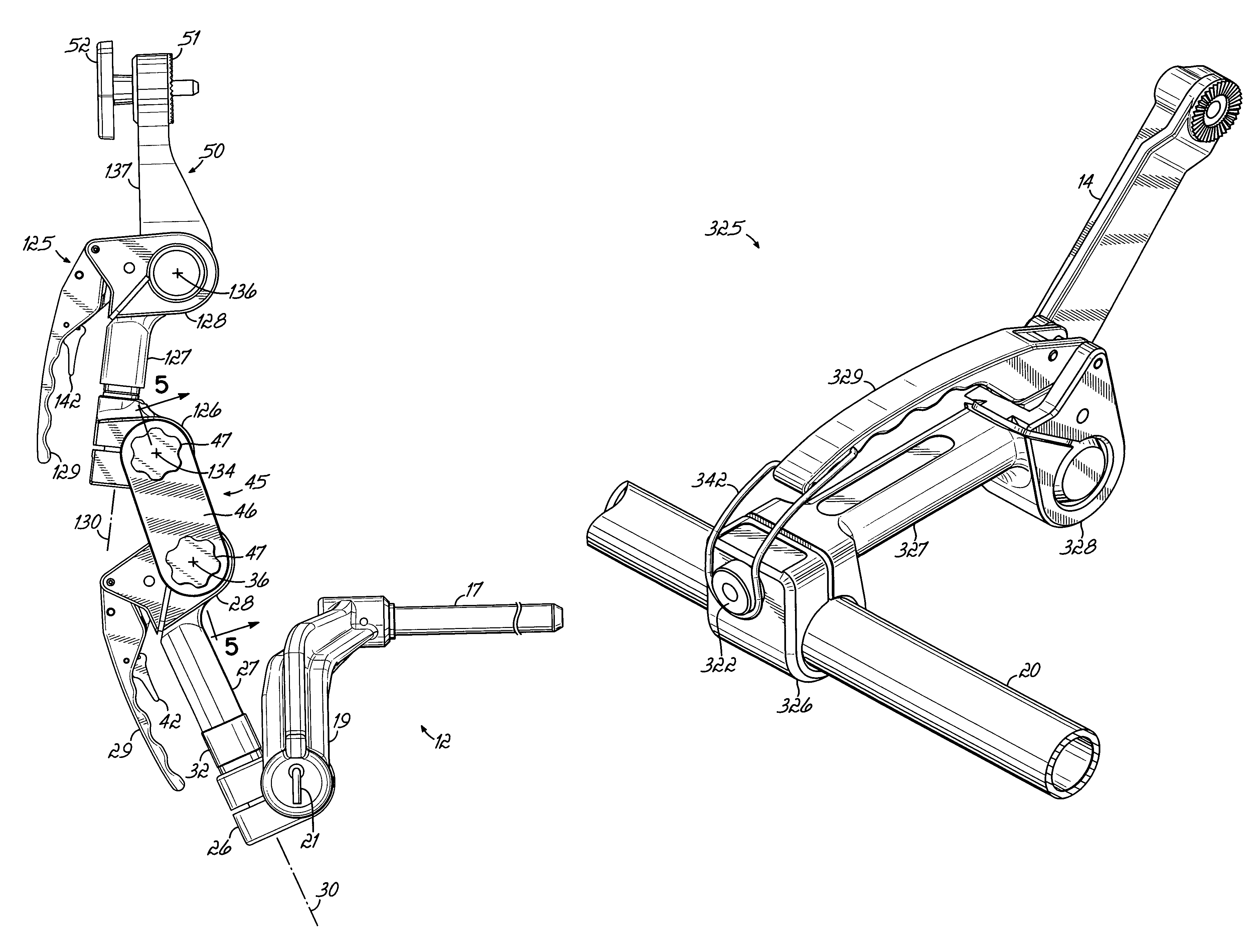
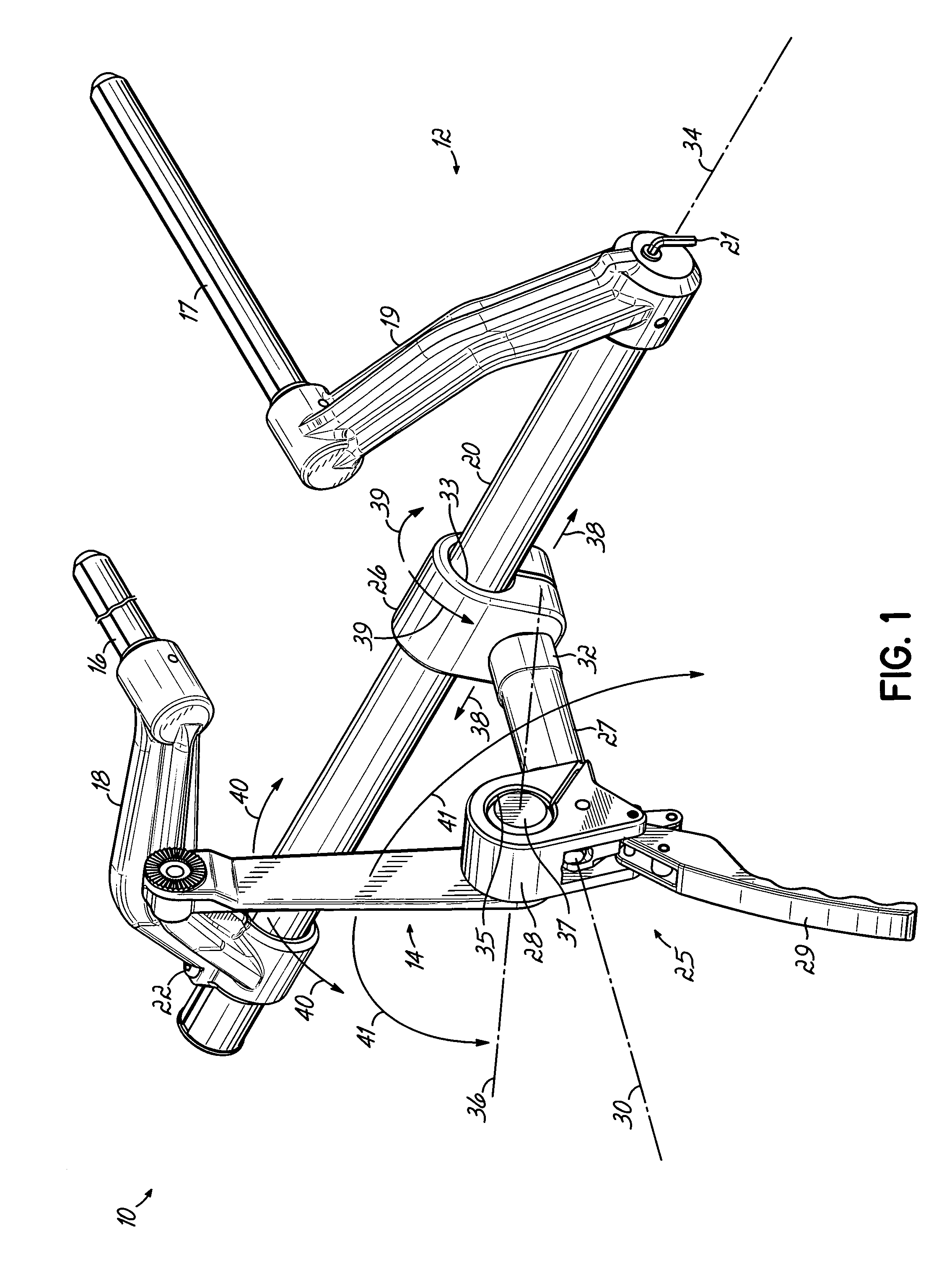
[0033]FIG. 1 shows a head support system 10 constructed in accordance with a first preferred embodiment of the invention, for holding the head of a patient (not shown) in a desired position relative to a medical table (not shown). The system 10 includes a base unit 12 and a conventional transition member 14. FIG. 1 shows that the primary advantages of the present invention can be achieved with relatively few components, and also by using some of the existing conventional cranial stabilization components, such as a conventional transition member 14.

[0034]The base unit 12 of the present invention includes a pair of spaced support rods, 16 and 17. A corresponding set of brackets 18 and 19, respectively, hold the support rods 16 and 17 in parallel. A crossbar 20, also sometimes referred to as a connecting tube, spans the horizontal distance between the brackets 18 and 19, and the brackets 18 and 19 hold the connecting tube 20 in a fixed position so that there is no relative rotation the...


PUM


Abstract

A head support base unit enables enhanced capability for positioning the head of a patient at the end of a medical table, by incorporating into the handle assembly thereof an additional degree of freedom, namely rotatability along the longitudinal axis of the handle. More specifically, a pair of axially opposed, spring-biased ratchets are housed within the handle, to permit or prevent axial rotation of one end of the handle relative to the other. This enhanced flexibility an maneuverability is achieved without any added complexity, and without requiring any additional space. These advantages are further magnified if an additional like handle assembly is connected to the first handle assembly, with a link interconnected therebetween, because composite angles and off-axis positioning of the patient can be readily accommodated.

Description

FIELD OF THE INVENTION[0001]This invention relates to a base unit for connecting a head holding device to a medical table, and more particularly, to a base unit which optimizes flexibility, maneuverability, and certainty locating and fixing the head holding device in a desired position relative to the medical table.BACKGROUND OF THE INVENTION[0002]The assignee of the present application owns U.S. Pat. No. 5,564,663, entitled “Transitional Pivot Joint For Head Support Base Unit,” which is expressly incorporated herein by reference, in its entirety (the “'663 patent”). The '663 patent shows a base unit which connects to a medical table. The base unit includes a crossbar and a handle assembly. A transition member connects to the handle assembly, and a swivel adaptor connects to the transition member. Typically, a head holding device, such as a skull clamp or a horseshoe headrest, connects to the swivel adaptor to hold the head of a patient in a desired position relative to the table. A...

Claims


Application Information

Patent Timeline
Patent Type & Authority Patents(United States)
IPC IPC(8): A61G13/12
CPCA61B19/203A61B90/14
Inventor ROLFES, SEANDINKLER, II, CHARLES E.
Owner INTEGRA LIFESCI
Why Eureka
Try Eureka