IT resource management system, IT resource management method, and IT resource management program

Inactive Publication Date: 2006-10-05
FUJITSU LTD
View PDF28 Cites 165 Cited by
  • Summary
  • Abstract
  • Description
  • Claims
  • Application Information

AI Technical Summary

Benefits of technology

[0017] According to the present invention, an IT resource management system, an IT resource management method, and an IT resou

Problems solved by technology

However, according to the above-mentioned conventional method, the assignment for an insufficient IT resource is merely conducted directly by the IDC, and the interchange of IT resources between corporations that are custo

Method used


Image

  • IT resource management system, IT resource management method, and IT resource management program
  • IT resource management system, IT resource management method, and IT resource management program
  • IT resource management system, IT resource management method, and IT resource management program

Examples


Example

Embodiment 1

[0053] Embodiment 1 is directed to an IDC of a utility system having a mechanism for distributing a surplus IT resource among corporations that are customers.

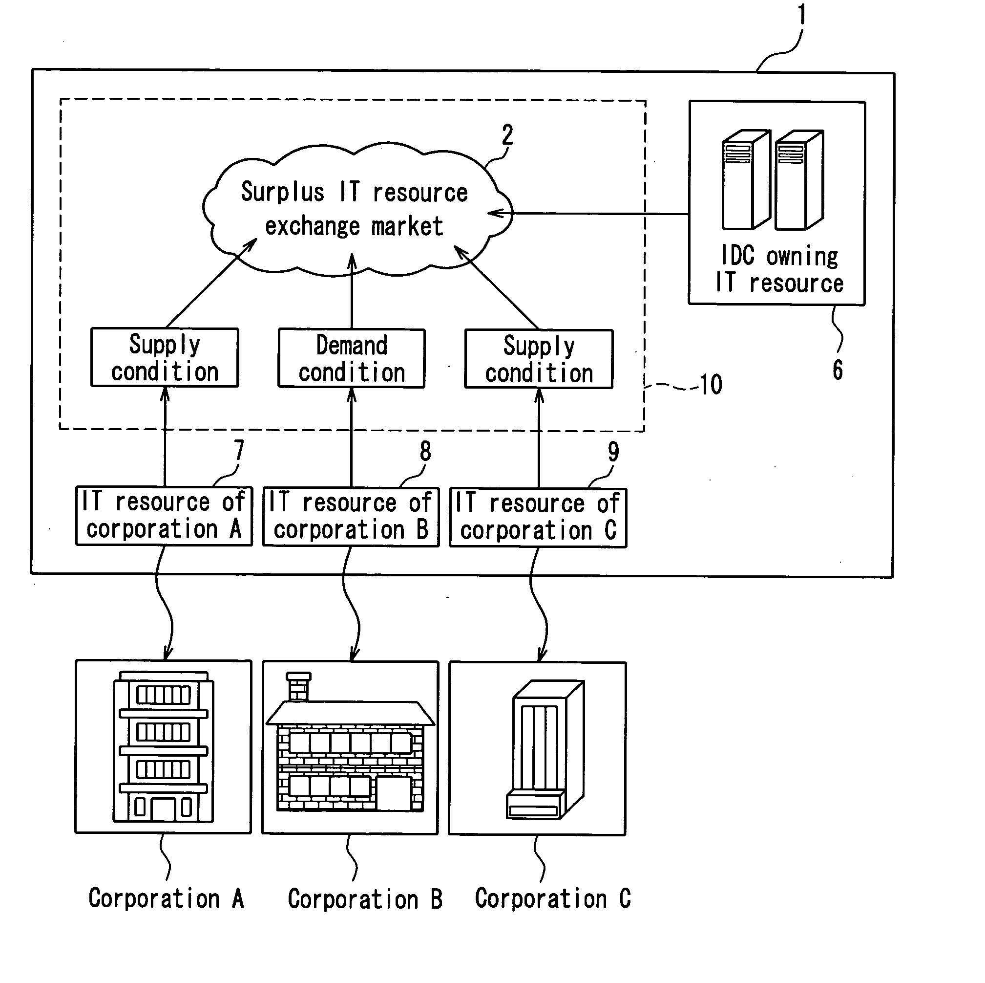
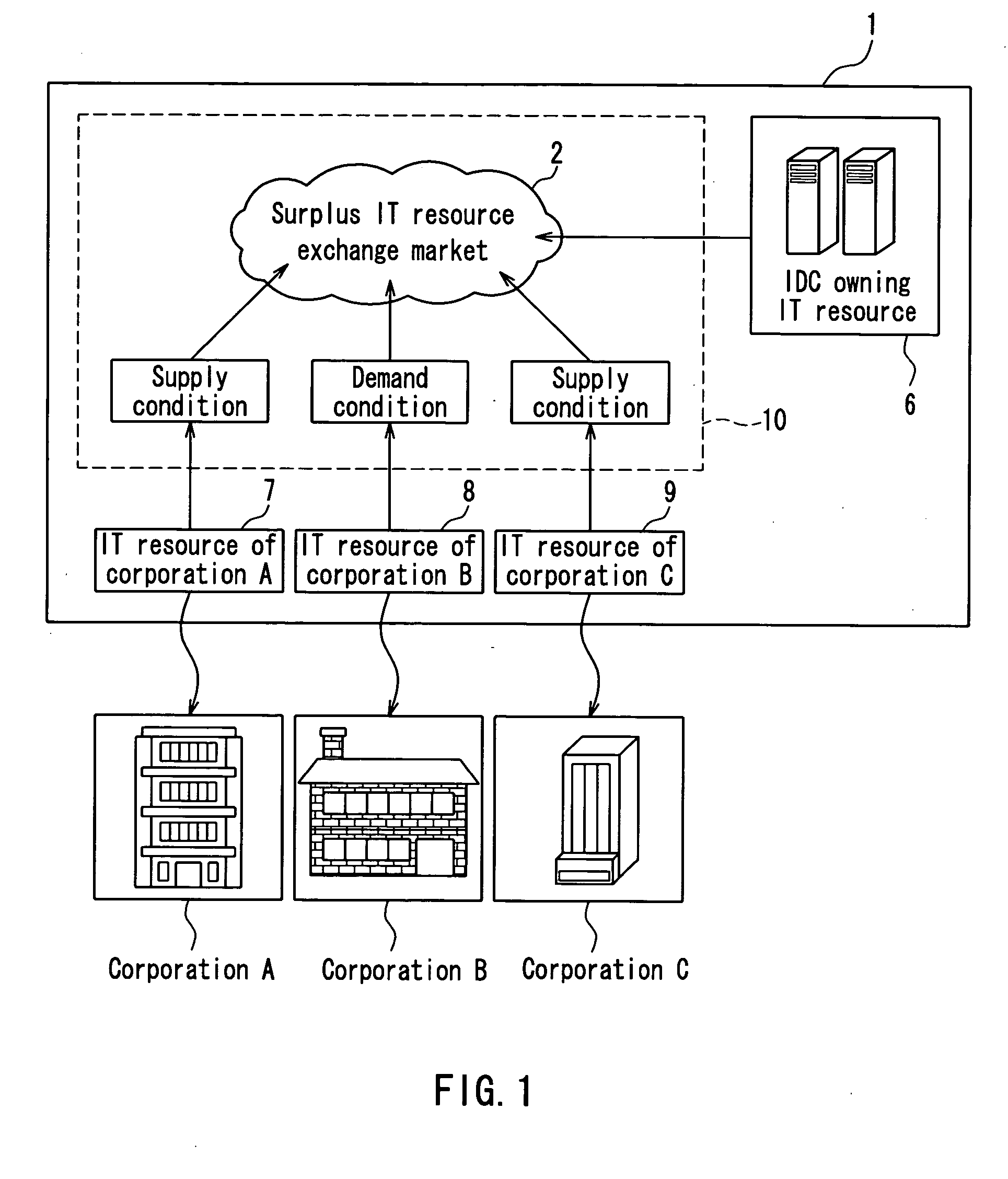
[0054]FIG. 1 is a conceptual diagram showing the concept of an entire configuration of an IDC 1 in the present embodiment.

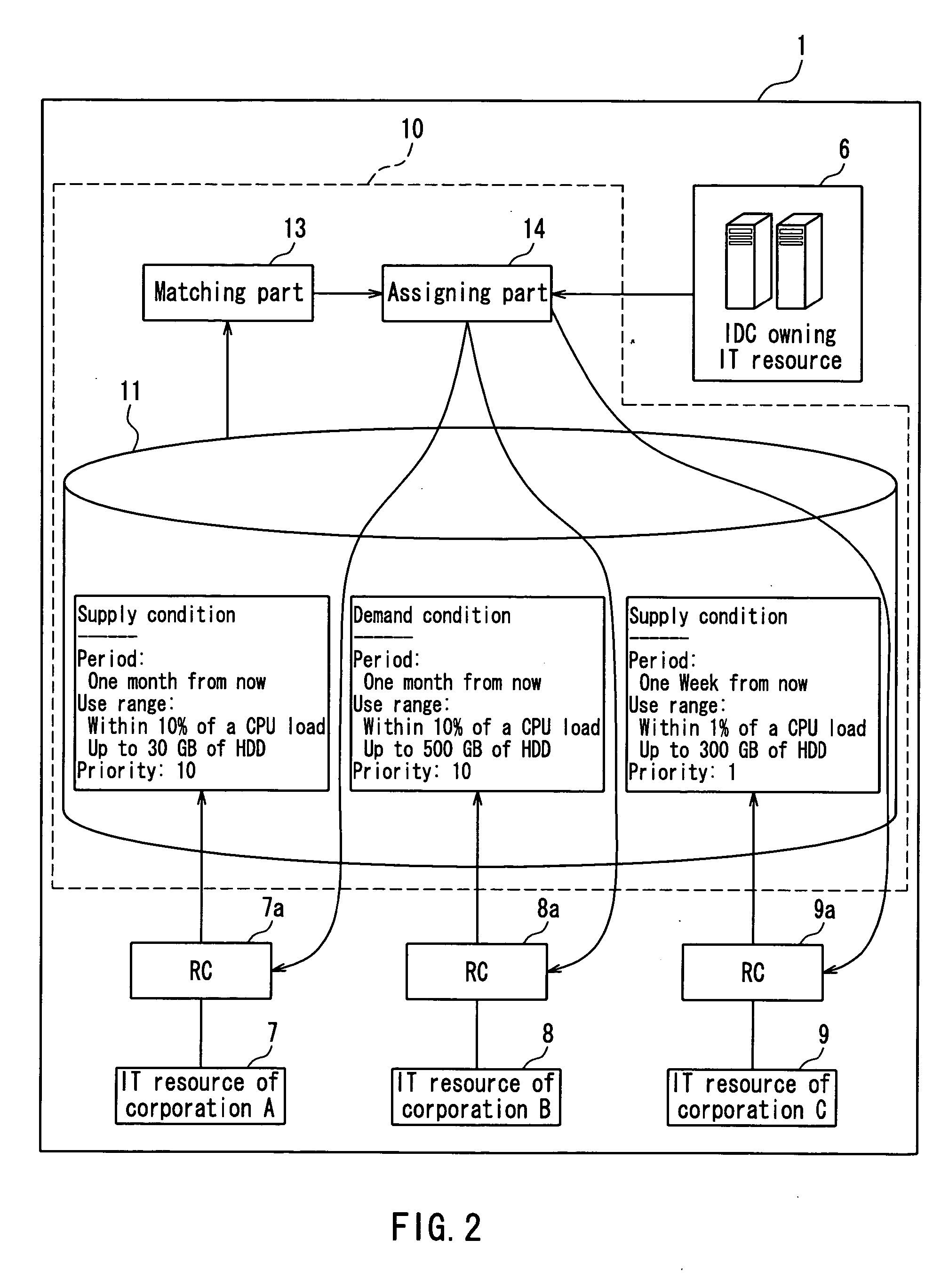
[0055] The IDC 1 manages IT resources 7, 8, and 9 of corporations A, B, and C that are customers. The IT resources 7, 8, and 9 can be increased / decreased on demand. The IDC 1 includes an IT resource management system 10 for distributing IT resources among different corporations. An exemplary operation conducted in the IT resource management system 10 will be described below.

[0056] Supply conditions of the IT resources 7, 9 are presented from the corporations A, C. The corporations A, C present the supply conditions (e.g., a CPU use ratio, the number of bytes used by a storage, a usable period, possible processing conditions (on-line / batch processing), etc.) of the IT resources 7, 9, which are...

Example

Embodiment 2

[0120] According to Embodiment 2, a merging function is added to the accumulating part 11 of the IT resource management system 10 according to Embodiment 1. The merging function is to integrate or merge demand conditions or supply conditions with the same or similar business policies to generate and accumulate virtual demand conditions or supply conditions.

[0121]FIG. 12 is a functional block diagram showing a configuration of an IDC 1 including an IT resource management system 20 in the present embodiment. The configuration and processing of the IT resource management system 20 in FIG. 12 are similar to those of the IT resource management system 10 in Embodiment 1 except for the following points, so that the description of the similar components will be omitted.

[0122] The IT resource management system 20 is different from the IT resource management system 10 in Embodiment 1 in that the IT resource management system 20 includes a merging part 19. The merging part 19 me...

Example

Embodiment 3

[0143] According to Embodiment 3, a fee calculating function is added to the IT resource management system according to Embodiment 2. The fee calculating function is to calculate a fee incurred when a corporation supplies or demands an IT resource.

[0144] The configuration and processing of the IT resource management system in the present embodiment are the same as those of the IT resource management system 20 in Embodiment 2 except that the IT resource management system in the present embodiment includes a fee calculating part, so that the description of the same components will be omitted.

[0145]FIG. 17 is a functional block diagram showing a configuration of an IDC 1 including an IT resource management system 30 according to the present embodiment.

[0146] The IT resource management system 30 further includes a fee calculating part 17. The fee calculating part 17 calculates a fee incurred when the corporations A, B, and C supply or demand the IT resources 7, 8, and 9 ...


PUM


Abstract

An IT resource management system for managing a plurality of IT resources owned by a plurality of operating entities includes a supply condition accumulating part for accumulating a supply condition of a surplus IT resource, a demand condition accumulating part for accumulating a demand condition of an insufficient IT resource, a matching part for extracting a set of a supply condition and a demand condition matched with each other from the supply conditions and the demand conditions accumulated in the accumulating parts, and an assigning part for allowing an IT resource under the supply condition of the set to be available for an operating entity under the demand condition of the set.

Description

BACKGROUND OF THE INVENTION [0001] 1. Field of the Invention [0002] The present invention relates to an IT resource management system for managing IT resources owned by a plurality of operating entities, for example, as in an Internet data center (hereinafter, referred to as an “IDC”). [0003] 2. Description of Related Art [0004] Regarding an information technology (IT) system forming the foundation of the economy and society, there is a requirement for stability, robustness, and economic efficiency. In recent years, in order to maintain the function of an IT system that is being sophisticated more and more in response to the change in an administration environment while keeping stability and robustness, the technique of autonomous processing of the system is becoming indispensable. The autonomous processing refers to that a system takes over a part of determination, which has been conducted by human beings. The autonomous processing enhances the ability of the system to respond to a...

Claims


Application Information

Patent Timeline
IPC IPC(8): G07G1/00G06Q10/00G06Q10/06G06Q50/00
CPCG06Q30/0283G06Q10/06
Inventor MATSUMOTO, YASUHIDEYASAKI, MASATOMO
Owner FUJITSU LTD
Why Eureka
Try Eureka