Humidity sensor for measuring supersaturated water vapor utilizing a mini-heater

a technology of supersaturated water vapor and humidity sensor, which is applied in the direction of material moisture content, sampling, instruments, etc., can solve the problems of erroneous readings, dissipation effect, and elements utilized as resistive components, and achieve the effect of reducing the relative humidity to the measurable level and minimizing the airflow

Inactive Publication Date: 2006-10-12
HONEYWELL INT INC
View PDF10 Cites 16 Cited by
  • Summary
  • Abstract
  • Description
  • Claims
  • Application Information

AI Technical Summary

Benefits of technology

[0017] In accordance with an alternative embodiment, the humidity sensor can be configured from a ceramic material having a plurality of holes formed therein which minimize airflow thereof, such that the ceramic material is nonconductive and heats and vaporizes water droplets passing therethrough, thereby reducing the relative humidity to the measurable level.

Problems solved by technology

It has been found, however, that elements utilized as resistive components suffer from the disadvantage that there is an inherent dissipation effect caused by the dissipation of heat due to the current flow in the elements necessary to make a resistance measurement.
The result is erroneous readings, among other problems.
In addition, there can also be inaccuracy incurred at high relative humidity values where high water content causes problems due to excessive stress and the resulting mechanical shifts in the components of the element.
One of the problems with RH sensors is such devices can measure RH up to 100%, but at levels higher than 100% water droplets generally form in a suspension (e.g., fog) and sensor fails to operate due to material limitations.
To date, a satisfactory solution has not been found for adequately measuring RH at levels higher than 100%.

Method used


Image

  • Humidity sensor for measuring supersaturated water vapor utilizing a mini-heater
  • Humidity sensor for measuring supersaturated water vapor utilizing a mini-heater
  • Humidity sensor for measuring supersaturated water vapor utilizing a mini-heater

Examples


Embodiment Construction

[0022] The particular values and configurations discussed in these non-limiting examples can be varied and are cited merely to illustrate at least one embodiment and are not intended to limit the scope thereof.

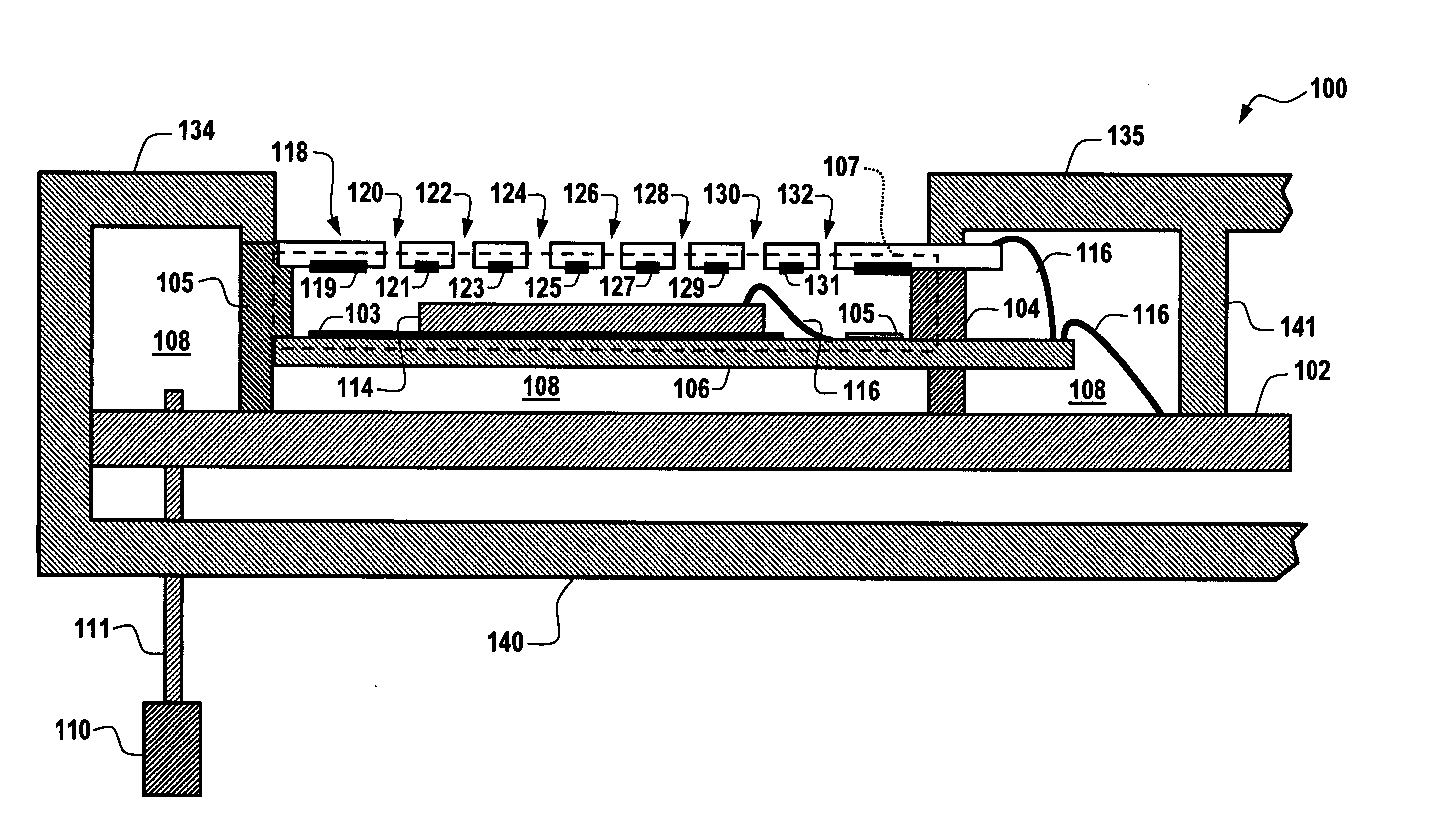
[0023]FIG. 1 illustrates a side view of a humidity sensor apparatus 100 that can be implemented in accordance with one embodiment. Apparatus 100 includes a humidity sensor 114 and a topside heater 118 comprising a material that permits diffusion of air through heater 118 and a bottom-side heater 106 located below humidity sensor 114. The topside heater 118 is located above humidity sensor 114 and includes a plurality of holes 120, 122, 124, 126, 128, 130 and 132. A sensing area 107 indicated by dashed lines in FIG. 1 is generally formed between the topside heater 118, the humidity sensor 114 and the bottom-side heater 106.

[0024] Topside heater 118 and bottom-side heater 106 together form a heater that surrounds the humidity sensor 114 and the sensing area 107. The sensing ar...


PUM

PropertyMeasurementUnit
relative humidityaaaaaaaaaa
RHaaaaaaaaaa
RHaaaaaaaaaa

Abstract

A humidity sensing apparatus and method includes a humidity sensor capable of measuring relative humidity and a heater located about and proximate to the humidity sensor wherein a portion of the heater comprises a material that permits a diffusion of air through the material of the heater. A sensing area is generally formed between the heater and the humidity sensor, wherein the heater provides a heated environment within the sensing area in order to evaporate water droplets that form within the sensing area and reduce relative humidity to a measurable level and measure supersaturated air within the sensing area.

Description

TECHNICAL FIELD [0001] Embodiments are generally related to sensing devices and components thereof. Embodiments additionally relate to humidity sensors and techniques for measuring water vapor. Embodiments also relate to heater components utilized in association with humidity sensors for measuring water vapor and humidity. BACKGROUND OF THE INVENTION [0002] Humidity sensors are but one class of sensors that are utilized in a variety of commercial and industrial applications. Humidity sensors are utilized to measure water vapor, which is an important factor in maintaining consumer and industrial products. Modern manufacturing processes, for example, generally require measurement of moisture contents corresponding to dew points between −40° C. and 18° C., or a relative humidity between 1% and 100%. There is also a need for a durable, compact, efficient moisture detector that can be used effectively in these processes to measure very small moisture content in gaseous atmospheres. Anoth...

Claims


Application Information

Patent Timeline
Patent Type & Authority Applications(United States)
IPC IPC(8): G01N7/00
CPCG01N2001/2229G01N25/68
Inventor SPELDRICH, JAMIE W.
Owner HONEYWELL INT INC
Why Eureka
Try Eureka