

Solar collector and method
a solar collector and collector technology, applied in the field of solar collectors, can solve the problems of fluid thawing uniformly in the fluid circuit, the inability of sunlight to be used for heating fluid, and the loss of thermal energy to the cooler ambient environmen
- Summary
- Abstract
- Description
- Claims
- Application Information
AI Technical Summary
Benefits of technology
Problems solved by technology
Method used
Image

Examples
Embodiment Construction
[0033] The present invention now will be described more fully hereinafter with reference to the accompanying drawings, in which some, but not all embodiments of the invention are shown. Indeed, this invention may be embodied in many different forms and should not be construed as limited to the embodiments set forth herein; rather, these embodiments are provided so that this disclosure will satisfy applicable legal requirements. Like numbers refer to like elements throughout.
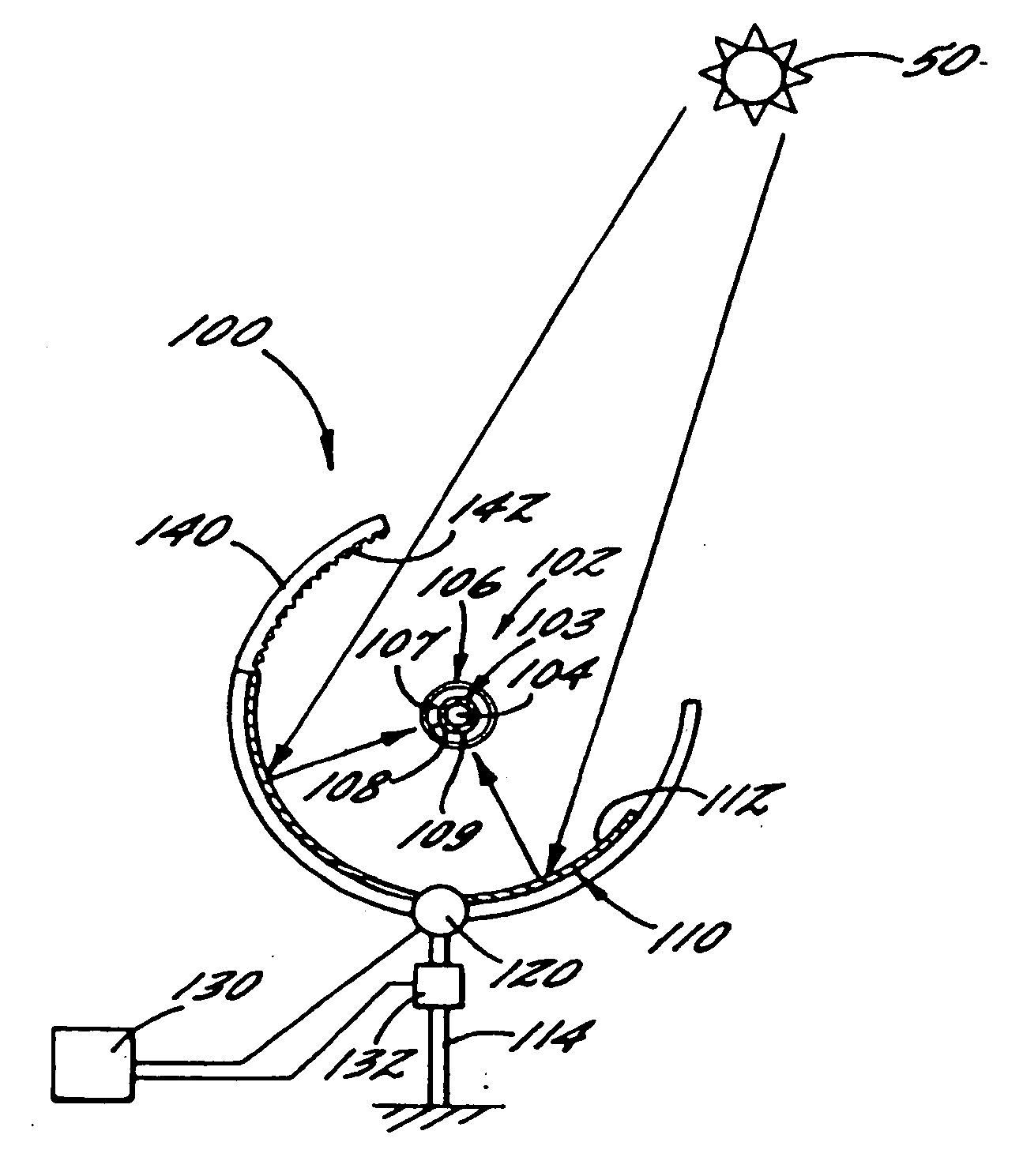
[0034] Referring now to FIG. 4, there is shown an apparatus 100 for collecting solar energy. The apparatus 100 is structured as a trough-type solar collector, which includes a receiver 102 such as a pipe, tube, or other fluid conduit or vessel that defines a passage 104 for receiving and heating the heat transfer fluid. The apparatus 100 also includes a concave collector mirror 110 with a reflective surface 112 that is directed toward the receiver 102 and configured to reflect solar radiation toward the receiver...
PUM
 Abstract
Description
Claims
Application Information