Solar collector and method

a solar collector and collector technology, applied in the field of solar collectors, can solve the problems of fluid thawing uniformly in the fluid circuit, the inability of sunlight to be used for heating fluid, and the loss of thermal energy to the cooler ambient environmen

Inactive Publication Date: 2006-06-06
UNITED TECH CORP +2
View PDF22 Cites 120 Cited by
  • Summary
  • Abstract
  • Description
  • Claims
  • Application Information

AI Technical Summary

Benefits of technology

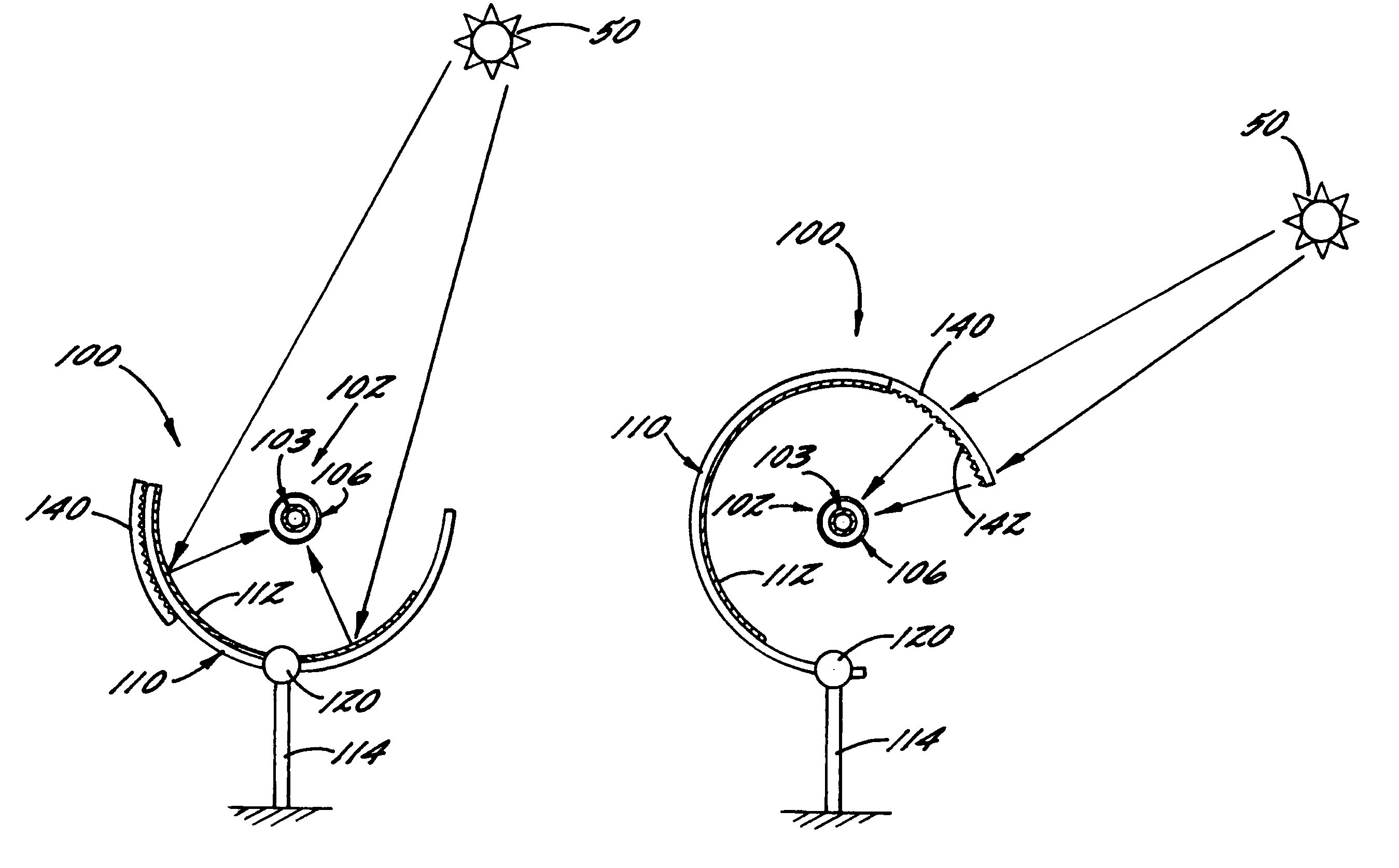
[0011]In embodiments that include a lens, the lens is adjustable between first and second positions. For example, the lens can be fixedly positioned and configured to direct solar radiation from a plurality of directions toward the receiver, and an adjustable shade can be provided to controllably prevent the transmission of solar radiation toward the receiver and thereby control the amount of heating of the receiver. Alternatively, the lens can be rotatable about a longitudinal axis of the receiver so that the lens can direct solar energy from the sun toward the receiver throughout a range of relative positions of the sun. In the first position the lens directs solar radiation toward the receiver to thereby heat the heat transfer fluid in the passage at a first rate, and in the second position the lens directs a lesser amount of solar radiation toward the receiver than in the first position to thereby heat the receiver at a second rate less than the first rate.
[0013]According to another embodiment of the present invention, the heat transfer fluid is circulated through the receiver and a solar collection apparatus is adjusted between first and second positions. In the first position, a lens of the apparatus is configured to direct, i.e., by refracting and concentrating, solar radiation toward the receiver and heat the heat transfer fluid therein. In the second position, the lens is configured to direct a second, lesser amount of solar radiation toward the receiver. The apparatus can be adjusted by rotating the lens about the receiver according to a relative position of the sun, and / or by adjusting a shade device to at least partially prevent the transmission of solar radiation toward the receiver.

Problems solved by technology

At times of relative darkness, such as at nighttime and during cloudy or otherwise overcast weather conditions, sunlight cannot be used for heating the fluid.
However, if the fluid is continuously circulated when the system 10 is receiving little or no sunlight, the fluid loses thermal energy to the cooler ambient environment.
Uniform thawing of the fluid in the fluid circuit 14 can be difficult, and the expansion of the fluid associated with freezing and / or thawing can over-stress, plastically deform, and eventually burst or otherwise destroy the receivers 18, and other components of the system 10.
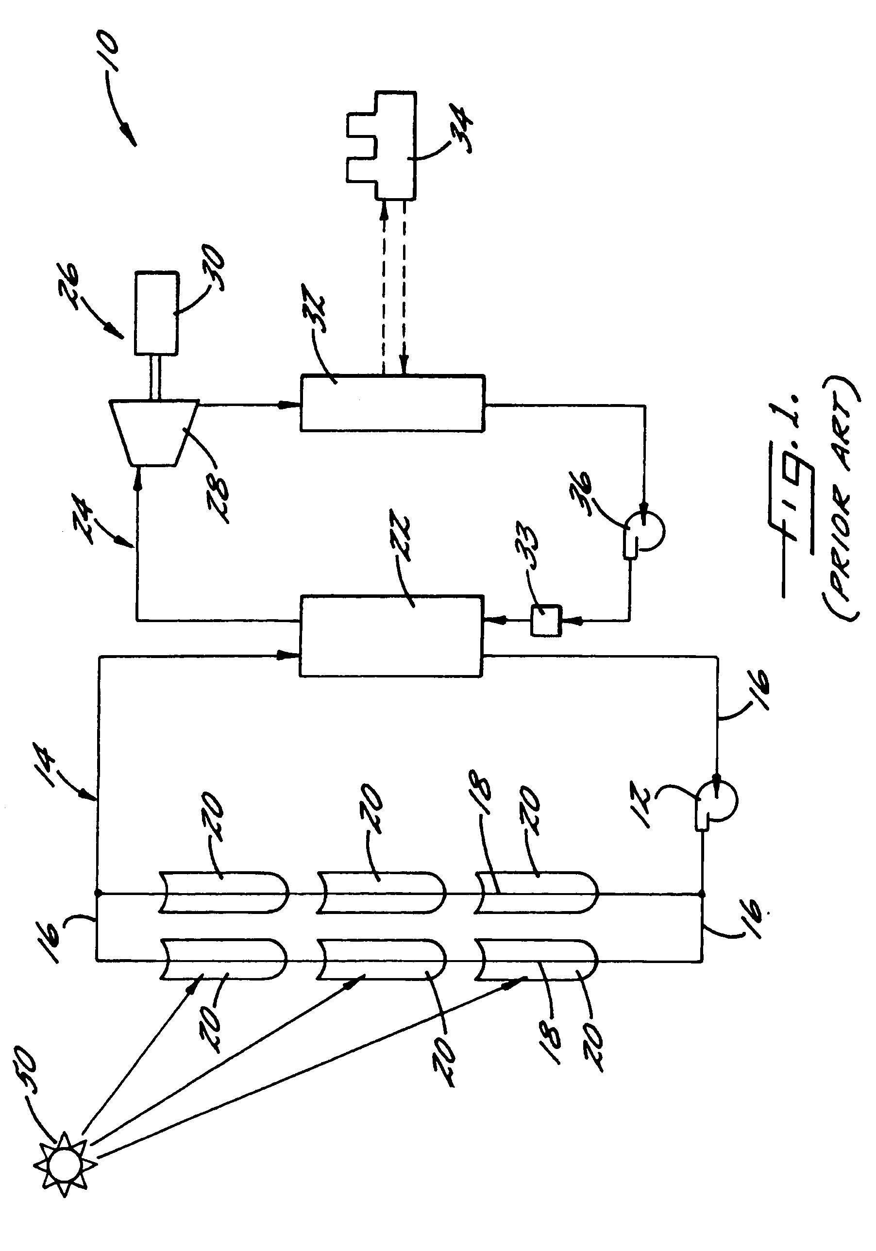
Therefore, in order to maintain the proper temperature of the fluid, the fluid is heated by electric or gas heaters as the fluid circulates around circuit 14, increasing the energy required for operating the system 10, reducing the overall efficiency, and adding pollutants to the environment.
Therefore, if the receivers 18 are emptied at the end of each day and refilled at the start of each subsequent day, it can be difficult using the system 20 to match the temperature of the fluid and the receivers 18 during the daily filling operation.

Method used


Image

  • Solar collector and method
  • Solar collector and method
  • Solar collector and method

Examples


Embodiment Construction

[0033]The present invention now will be described more fully hereinafter with reference to the accompanying drawings, in which some, but not all embodiments of the invention are shown. Indeed, this invention may be embodied in many different forms and should not be construed as limited to the embodiments set forth herein; rather, these embodiments are provided so that this disclosure will satisfy applicable legal requirements. Like numbers refer to like elements throughout.

[0034]Referring now to FIG. 4, there is shown an apparatus 100 for collecting solar energy. The apparatus 100 is structured as a trough-type solar collector, which includes a receiver 102 such as a pipe, tube, or other fluid conduit or vessel that defines a passage 104 for receiving and heating the heat transfer fluid. The apparatus 100 also includes a concave collector mirror 110 with a reflective surface 112 that is directed toward the receiver 102 and configured to reflect solar radiation toward the receiver 10...


PUM


Abstract

An apparatus and method for collecting solar energy are provided. The apparatus is a trough-type solar collector having one or more mirrors and lenses for directing solar radiation toward a receiver configured to receive a heat transfer fluid therein. The amount of solar radiation directed toward the receiver can be controlled by adjusting one or more of the mirrors and / or lenses or by adjusting a shade. Thus, the collector can direct different amounts or solar radiation toward the receiver, thereby selectively heating the receiver at different rates, e.g., to preheat the receiver, to heat fluid in the receiver for power generation, or to thaw solidified fluid in the receiver. Subsequently, the heated fluid can be used to generate steam and / or electricity.

Description

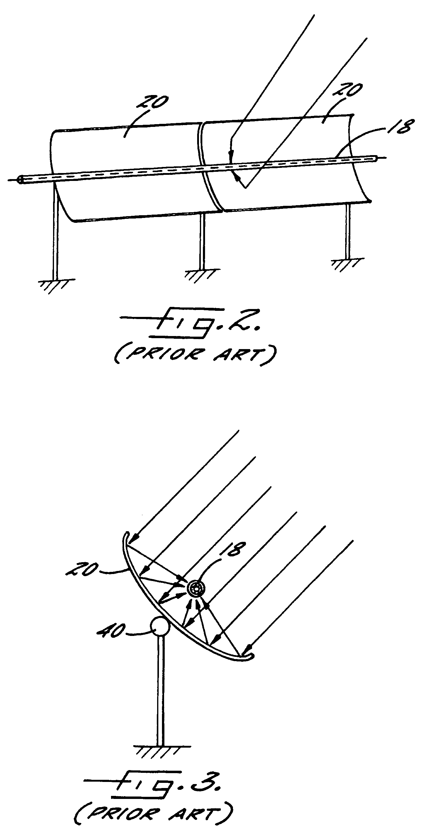
BACKGROUND OF THE INVENTION[0001]1) Field of the Invention[0002]The present invention relates to the solar energy devices, and, in particular, relates to a trough solar collector that can be used to collect solar energy for power generation.[0003]2) Description of Related Art[0004]In a conventional trough-type solar power generation system 10, as illustrated in FIG. 1, a plurality of parabolic collector mirrors 20 are used to reflect sunlight toward receivers 18 in which a heat transfer fluid is circulated. The fluid, which can be organic or synthetic oil, is circulated by a pump 12 through a fluid circuit 14 that includes the receivers 18 and a plurality of connection pipes 16. After being heated by the collector mirrors 20, the fluid is delivered to a steam generator 22, in which thermal energy is exchanged from the heat transfer fluid to water in a separate fluid circuit 24. Thus, the heat transfer fluid is cooled in the steam generator 22 and can then be re-circulated to the rec...

Claims


Application Information

Patent Timeline
Patent Type & Authority Patents(United States)
IPC IPC(8): F24J2/08F24J2/40F24S23/30F24S23/74F24S50/20
CPCF24J2/085F24J2/14F24J2/407F24J2/541F24J2/4649Y02E10/47Y02E10/43Y02E10/45F24S23/31F24S23/74F24S30/425F24S40/60F24S50/80F24S80/20Y02E10/40
Inventor LITWIN, ROBERT Z.
Owner UNITED TECH CORP
Why Eureka
Try Eureka