Snap on strainer with side-slide cleaning

a strainer and side-slide technology, applied in the field of strainers, can solve the problems of strainer devices, cumbersome and tedious methods of most strainers, and the lack of strainer knowledg

Active Publication Date: 2006-10-12
XYLEM IP HLDG
View PDF18 Cites 4 Cited by
  • Summary
  • Abstract
  • Description
  • Claims
  • Application Information

AI Technical Summary

Benefits of technology

[0015] One advantage of the strainer device according to the present invention is that the strainer cover assembly may be manufactured to include screens having different filtering properties.

Problems solved by technology

Most strainers known in the art and found in the marketplace have very cumbersome and tedious methods like bayonet latch, threaded bowl, screws, etc. for fastening the strainer cover to the strainer housing.
Some of the shortcomings include that the known strainer devices are hard to open and close to clean the strainer, have to connect and disconnect the entire strainer assembly from the plumbing to clean, and require cleaning the strainer by touching / handling the contaminated metal screen.

Method used


Image

  • Snap on strainer with side-slide cleaning
  • Snap on strainer with side-slide cleaning
  • Snap on strainer with side-slide cleaning

Examples


Embodiment Construction

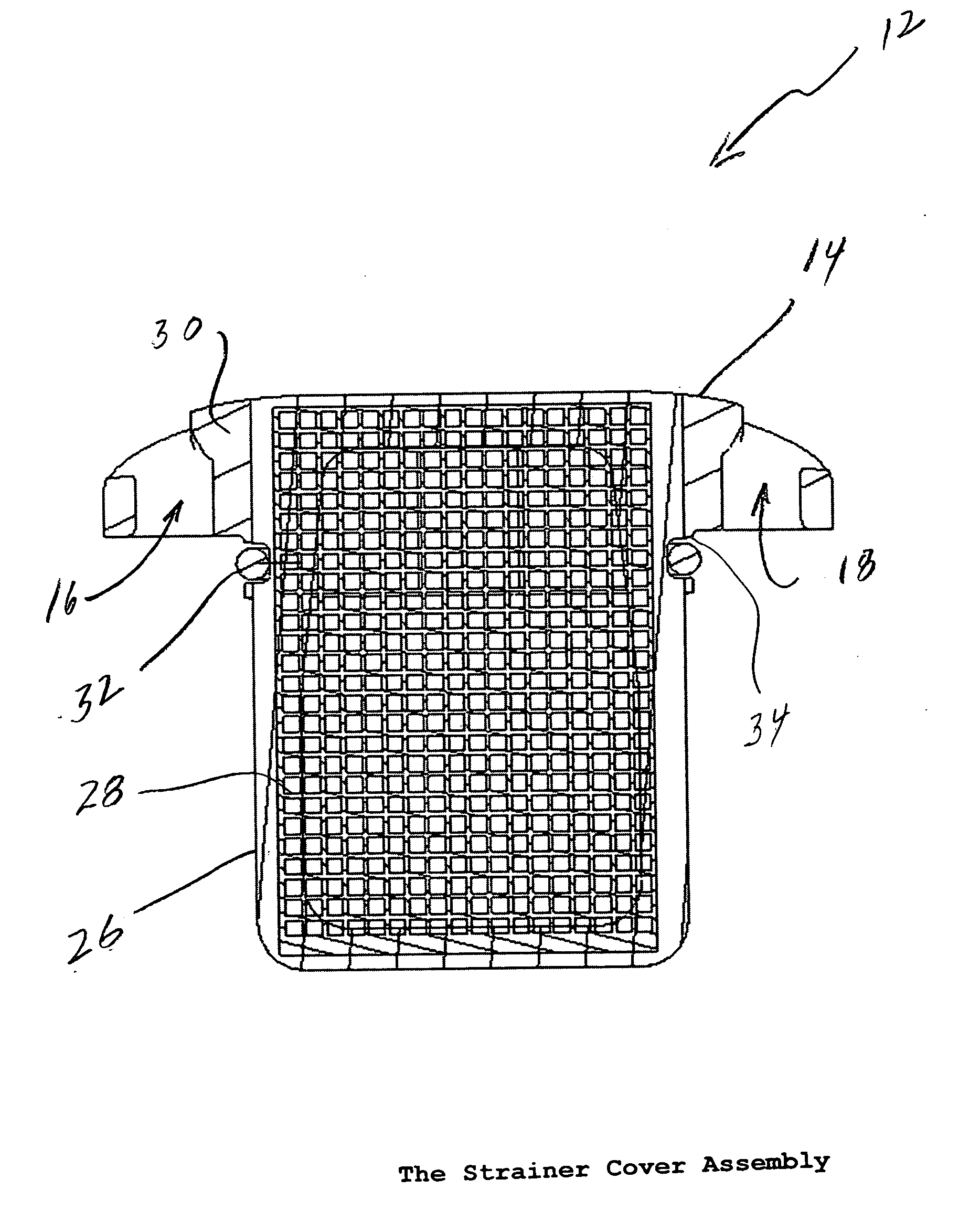
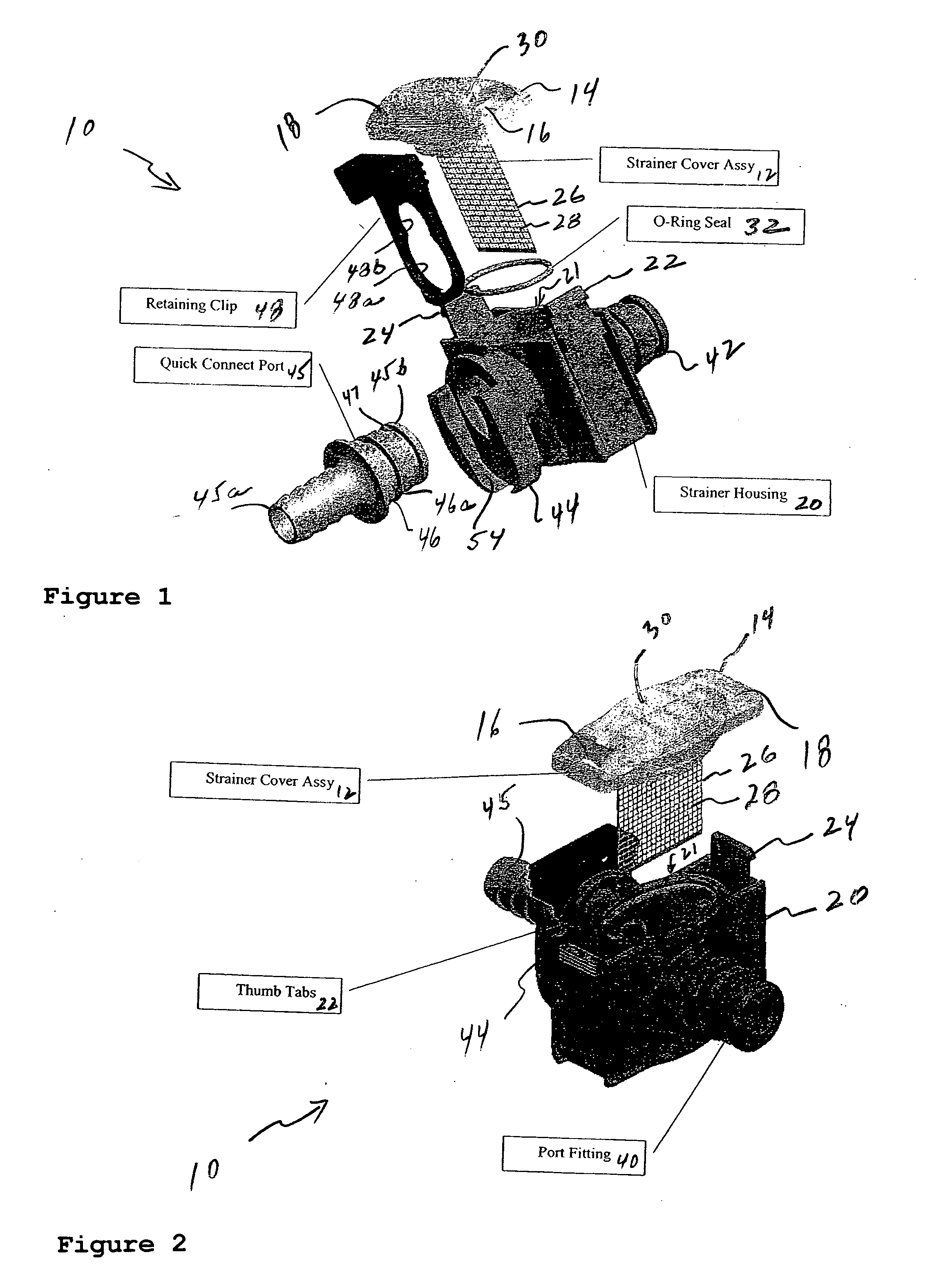
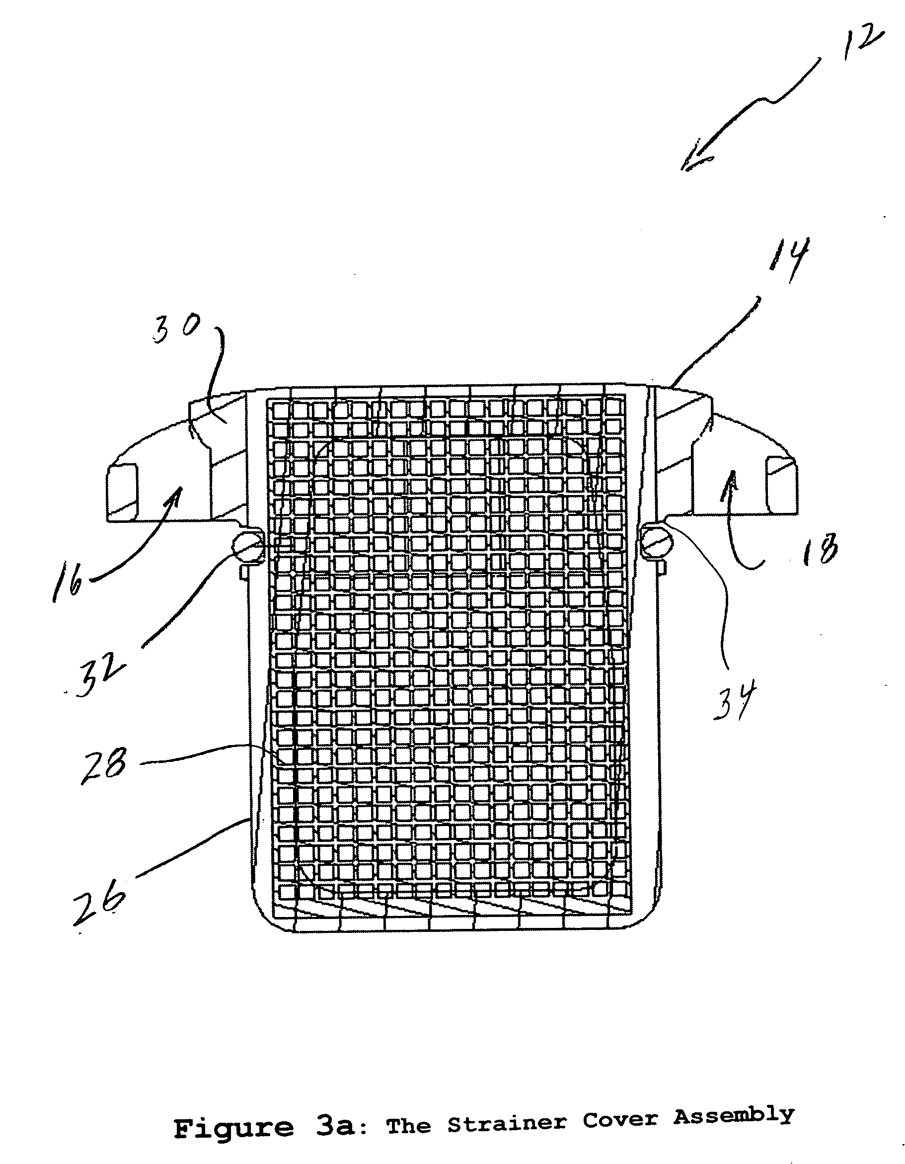
[0020] The present invention features a strainer device generally indicated as 10 having a strainer cover assembly 12 having a strainer cover 14 with tab openings 16, 18 (see also FIGS. 3a and 3b), and a strainer housing 20 having flexible tabs 22, 24 arranged thereon. In operation, the flexible tabs 22, 24 pass through the tab openings 16, 18 and fasten on the strainer cover assembly 12 to the strainer housing 20 with a snap action when the strainer cover assembly 12 is inserted into a housing opening 21 (see also FIG. 4). The flexible tabs 22, 24 are deflected for removing the strainer cover assembly 12.

[0021] The strainer cover assembly 12 includes a strainer portion 26 having a screen 28 for filtering a medium passing through the device, as best shown in FIG. 3. The scope of the invention is not intended to be limited to the type or kind of medium being strained or filtered. The snap action of the flexible tabs 22, 24 makes it easy to open, slide out and clean the screen 28 on ...


PUM

PropertyMeasurementUnit
flexibleaaaaaaaaaa
plasticaaaaaaaaaa
dimensionsaaaaaaaaaa

Abstract

The present invention features a device having a strainer cover assembly having a strainer cover with tab openings, and a strainer housing having flexible tabs arranged thereon, the flexible tabs passing through the tab openings and fastening on the strainer cover with a snap action. The flexible tabs are deflected for removing the strainer cover. The strainer cover assembly includes a strainer with a screen for filtering a medium passing through the device. The snap action of the flexible tabs makes it easy to open, slide out and clean the screen on the strainer cover assembly. The strainer cover assembly and the screen may be formed as an integral unit, which helps in cleaning the screen. In operation, the user simply compresses the snap tabs and slides out the screen which is attached to the strainer cover assembly and rinses the contaminated screen while holding it by the strainer cover assembly. The integral unit being formed by plastic mold injection. The screen may be made of stainless steel material. The strainer cover assembly may be made of a clear plastic material.

Description

CROSS-REFERENCE TO RELATED APPLICATIONS [0001] This application relates to provisional patent application Ser. No. 60 / 661,986, filed on 14 Mar. 2005, which is hereby incorporated by reference in their entirety.BACKGROUND OF THE INVENTION [0002] 1. Field of the Invention [0003] The present invention relates to a strainer; and more particularly relates to a strainer for low flow pumping applications. [0004] 2. Brief Description of Related Art [0005] Most strainers known in the art and found in the marketplace have very cumbersome and tedious methods like bayonet latch, threaded bowl, screws, etc. for fastening the strainer cover to the strainer housing. [0006] Some of the shortcomings include that the known strainer devices are hard to open and close to clean the strainer, have to connect and disconnect the entire strainer assembly from the plumbing to clean, and require cleaning the strainer by touching / handling the contaminated metal screen. [0007] There is a need in the industry fo...

Claims


Application Information

Patent Timeline
Patent Type & Authority Applications(United States)
IPC IPC(8): B01D24/00
CPCB01D29/01B01D2201/305B01D29/96
Inventor MIR, ASHFAQ
Owner XYLEM IP HLDG
Why Eureka
Try Eureka