Air-assisted agitation for tanks of application equipment

a technology of application equipment and air-assisted agitation, which is applied in the direction of broadcast seeders, mixers, sowing, etc., can solve the problems of inability to effectively break up all agglomerations and bridges, difficulty in moving the remaining material within the tank, and mechanical agitators are unable to assist in this task, so as to reduce the formation of agglomerations and/or bridges and effectively clean out the remaining particulate material within the tank

Active Publication Date: 2020-06-23
CNH IND CANADA
View PDF22 Cites 3 Cited by
  • Summary
  • Abstract
  • Description
  • Claims
  • Application Information

AI Technical Summary

Benefits of technology

[0009]The conveying system includes a pneumatic agitation system operably connected to the tanks of the applicator to agitate the particulate material disposed within the tanks in order to reduce the formation of agglomerations and / or bridges of particles within the tanks or to distribute the material during sectional control. The pneumatic agitation system includes a number of nozzles connected to each tank that are in turn connected to a pressurized air source and a controller. The controller is operable to selectively cause pressurized air to flow into the tanks through the nozzles to agitate the particulate material positioned therein, thereby breaking up any agglomerations of material within the tanks. The positioning of the nozzles enables the air flows from the nozzles to reach all internal areas of the tank in order to access material across the entire interior of the tank. Due to the configuration of the nozzles, the pneumatic agitation system can be operated at the end of a run in order to effectively clean out the particulate material remaining within the tank after the run has been completed.

Problems solved by technology

However, as the placement of the mechanical agitators within the tank limits their ability to agitate material that is not immediately adjacent the agitator, in certain situations all agglomerations and bridges cannot be broken up effectively, or to distribute material that has an uneven horizontal profile due to previous sectional control.
Further, when the material within the tank drops below a certain level, it is often difficult to move the remaining material within the tank into a position where the material can exit the tank, which requires that the tank be manually cleaned and / or emptied at the end of a run.
The mechanical agitators are unable to assist with this task as the remaining material rest outside of the operational volume that can be affected by the agitators, and may hinder the process by obstructing areas where the remaining material is positioned within the tank.

Method used


Image

  • Air-assisted agitation for tanks of application equipment
  • Air-assisted agitation for tanks of application equipment
  • Air-assisted agitation for tanks of application equipment

Examples


Embodiment Construction

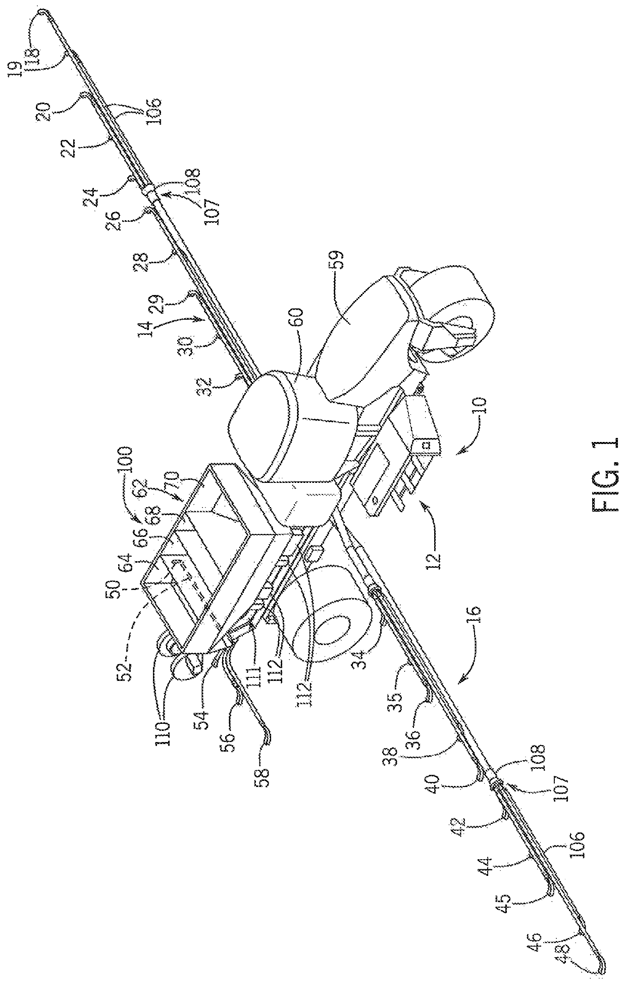
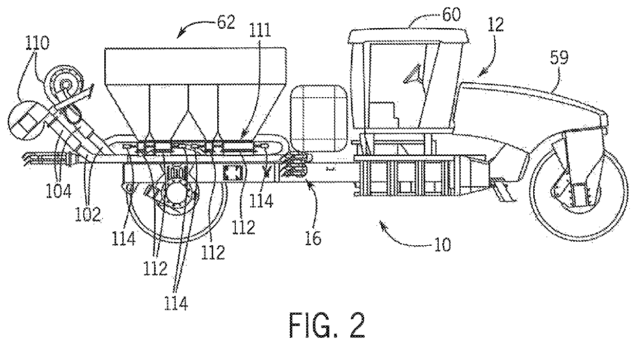
[0025]Referring now to the drawings, and more particularly to FIGS. 1-3, there is shown an agricultural application implement 10, on which a pneumatic conveying system 100 can be used. In the exemplary embodiment shown, application implement 10 is a granular fertilizer applicator 10. As is known in the art, applicator 10 generally includes a large tired transport unit 12 such as truck or tractor, and laterally extending particle delivery booms 14 and 16, which may be pivoted to a stowed position close to the implement for storage or transport. Each boom 14, 16 includes a plurality of boom tubes or conduits terminating at the outboard end in a particle delivering unit, which for fertilizer applicator 10 are a spreading outlet or nozzle. In the exemplary embodiment shown, boom 14 includes ten nozzles 18, 19, 20, 22, 24, 26, 28, 29, 30 and 32; and boom 16 includes ten nozzles 34, 35, 36, 38, 40, 42, 44, 45, 46 and 48. Additionally, at the back of applicator 10 there are five rear nozzl...


PUM


Abstract

The present invention is directed to an applicator having an agricultural product mechanical conveying system which transfers particulate material from one or more source containers to application equipment on demand, and meters the material at the application equipment. The conveying system includes a pneumatic agitation system operably connected to the tanks of the applicator to agitate the particulate material disposed within the tanks in order to reduce the formation of agglomerations and / or bridges of particles within the tanks. The pneumatic agitation system includes a number of nozzle connected to each tank that are in turn connected to a pressurized air source and a controller. The controller is operable to selectively cause pressurized air to flow into the tanks through the nozzles to agitate the particulate material positioned therein, thereby breaking up and agglomerations of material within the tanks.

Description

FIELD OF THE DISCLOSURE[0001]The present invention relates generally to agricultural equipment, and, more particularly, to an agricultural product delivery system on an application implement, such as a planter or fertilizer application equipment, for applying particulate material such as seed, fertilizer, herbicide or insecticide in a field, either as a surface application or deposited in the soil to improve soil quality.BACKGROUND OF THE DISCLOSURE[0002]Agricultural product delivery systems are known to utilize various mechanisms, including mechanical and pneumatic systems, i.e., a flow of air, to assist in the delivery and movement of particulate material or product such as fertilizer, seed, insecticide or herbicide from a product supply chamber through an interior passage provided by a series of elongate tubes which extend from the product supply chamber to a product applicator that places the product on or in growing medium, such as soil. Such agricultural product delivery syste...

Claims


Application Information

Patent Timeline
Patent Type & Authority Patents(United States)
IPC IPC(8): A01C15/00B01F15/04B01F15/00B01F15/02B01F13/00B01F13/02A01C7/08B65G53/42A01C15/04B01F33/40
CPCB01F15/00155B01F13/0277B01F13/0294B01F13/0266B01F15/0412B01F15/028B01F13/0227B01F15/00253B01F13/0037A01C15/007A01C15/04A01C7/082B65G53/42B01F33/5021B01F33/4062B01F33/408B01F33/4094B01F35/2112B01F33/404B01F35/83B01F35/2209B01F35/7543
Inventor ROBERGE, MARTIN J.DENIS, JOELRUPPERT, REX L.
Owner CNH IND CANADA
Why Eureka
Try Eureka