
RFID conveyor system

a conveyor system and conveyor technology, applied in the direction of conveyors, individually energized antenna arrays, instruments, etc., can solve the problems of barcode systems, although they have developed to a high degree of reliability

Inactive Publication Date: 2006-10-12
DATALOGIC AUTOMATION
View PDF28 Cites 49 Cited by
  • Summary
  • Abstract
  • Description
  • Claims
  • Application Information

AI Technical Summary

Problems solved by technology

Barcode systems, although having developed to a high degree of reliability, suffer from certain inherent limitations in that they require a line of sight between the barcode scanner and the label, and the barcode label must be applied on the package so as to be optically readable.

Method used


Image

  • RFID conveyor system
  • RFID conveyor system
  • RFID conveyor system

Examples


Embodiment Construction

[0054] Reference will now be made in detail to presently preferred embodiments of the invention, one or more example of which are illustrated in the accompanying drawings. Each example is provided by way of explanation of the invention, not limitation of the invention. In fact, it will be apparent to those skilled in the art that modifications and variations can be made in the present invention without departing from the scope or spirit thereof. For instance, features illustrated or described as part of one embodiment may be used on another embodiment to yield a still further embodiment. Thus, it is intended that the present invention covers such modifications and variations as come within the scope of the present disclosure.

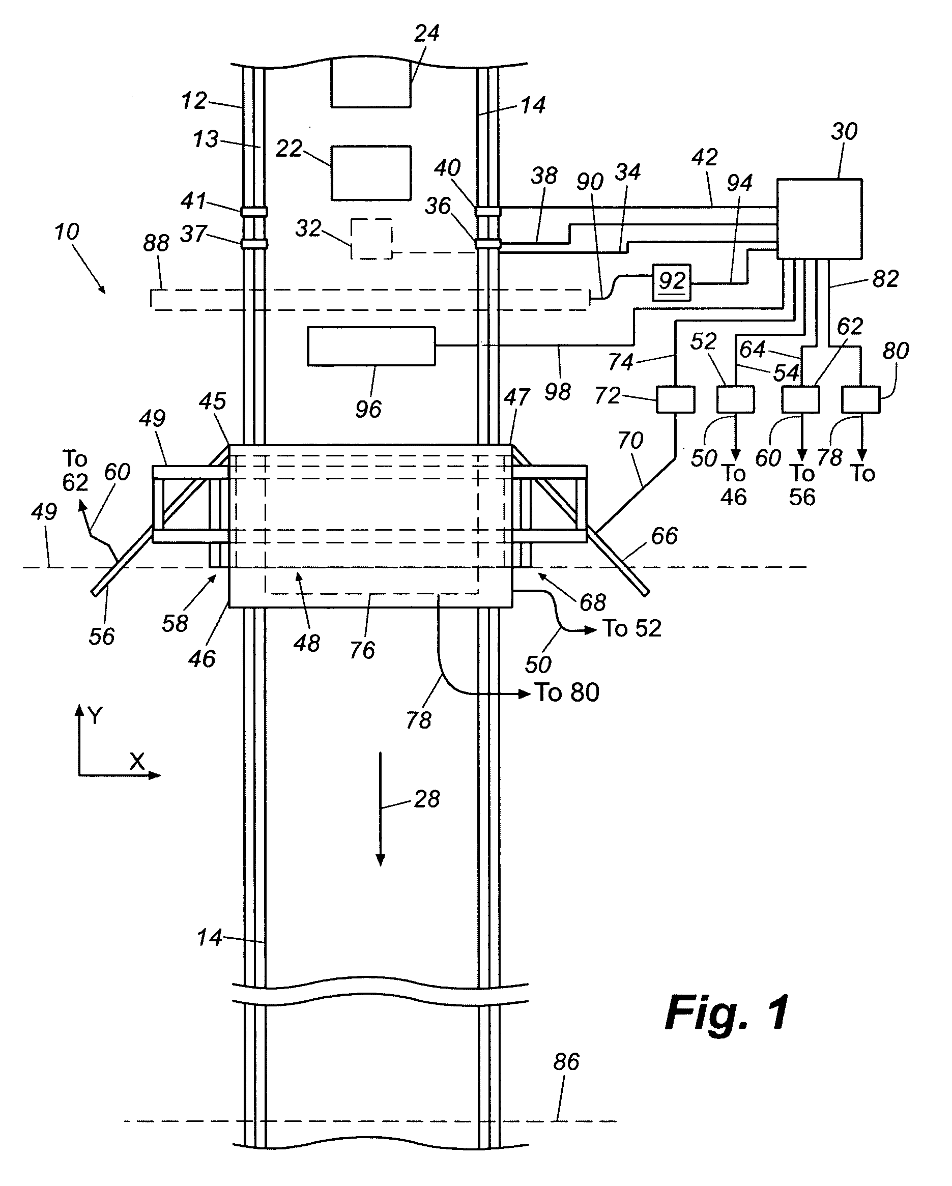
[0055] Referring to FIG. 1, a conveyor system 10 includes a belt 14 and a frame 12 that defines a generally planar horizontal top surface 13 extending the length of the conveyor and over which belt 14 carries a plurality of successive packages, e.g. boxes 22 an...


PUM


Abstract

A conveyor system for processing items on which radio frequency identification tags are disposed includes a frame having a generally planar top surface, a generally planar belt that is disposed moveably on the frame above the top surface and that conveys items through a path of travel, each item having at least one respective radio frequency identification tag disposed thereon. At least one antenna is disposed on the frame so that the antenna extends above the generally planar top surface between the generally planar top surface and the belt, the at least one antenna being oriented with respect to the belt so that the at least one antenna radiates radio frequency signals into a first area that is proximate the belt and through which the items pass and receives responses to the radio frequency signals from radio frequency identification tags on the items.

Description

[0001] The present application claims priority to U.S. Provisional Application No. 60 / 666,938, entitled RFID Tracking System and filed Mar. 29, 2005, and U.S. Provisional Application No. 60 / 773,634, entitled RFID Tracking System and filed Feb. 15, 2006, the entire disclosure of each of which is incorporated by reference herein.BACKGROUND OF THE INVENTION [0002] Most item tracking systems in commercial settings can be classified as either a supply chain system or a manufacturing system. Manufacturing systems generally track items that remain within a facility, whereas supply chain systems generally track items that move into, through and out of a facility. One common supply change system is a distribution center conveyor system on which boxes or other packages from a receiving area are placed and transported to one or more stations at which the packages are identified, sorted and distributed to appropriate locations depending on the sortation. It is well known in such systems to empl...

Claims


Application Information

Patent Timeline
IPC IPC(8): G08B13/14
CPCB07C5/3412H01Q21/28G06K7/0008G06K7/10079G06K7/10316G06K7/10336G06K7/10346G06K7/10356G06K7/10435G06K17/00G06K2017/0045G06K2017/0048G06K2207/1012G06Q10/08H01Q1/22H01Q1/2208H01Q1/2216H01Q1/2241H01Q9/0407H01Q9/0428H01Q17/001H01Q21/065H01Q21/08B65G2203/042
Inventor HILLEGASS, RAYMOND R.
Owner DATALOGIC AUTOMATION
Features
  • Generate Ideas
  • Intellectual Property
  • Life Sciences
  • Materials
  • Tech Scout
  • Unparalleled Data Quality
  • Higher Quality Content
  • 60% Fewer Hallucinations
Learn More