Lamp having outer shell to radiate heat of light source

Inactive Publication Date: 2006-10-12
TOSHIBA LIGHTING & TECH CORP
View PDF20 Cites 436 Cited by
  • Summary
  • Abstract
  • Description
  • Claims
  • Application Information

AI Technical Summary

Benefits of technology

[0016] In an embodiment of the invention, the cover is used to cover and protect the light source. The cover may be shaped in a globe or a shade. If the cover is the globe, a light reflection film may be provided on a part of the inside surface of the globe. The cover may be shaped optionally to diffuse or condense the light emitted from the light source. The cover may be either translucent or transparent. A lens to condense or diffuse the light from the light source may be used as the cover.
[0017] According to an embodiment of the invention, the heat generated by the light source during lighting is transmitted from the light source s

Problems solved by technology

This makes the heat radiating surface stain finish,

Method used


Image

  • Lamp having outer shell to radiate heat of light source
  • Lamp having outer shell to radiate heat of light source
  • Lamp having outer shell to radiate heat of light source

Examples


first embodiment

[0049] the present invention will be explained hereinafter with reference to FIG. 1 to FIG. 5.

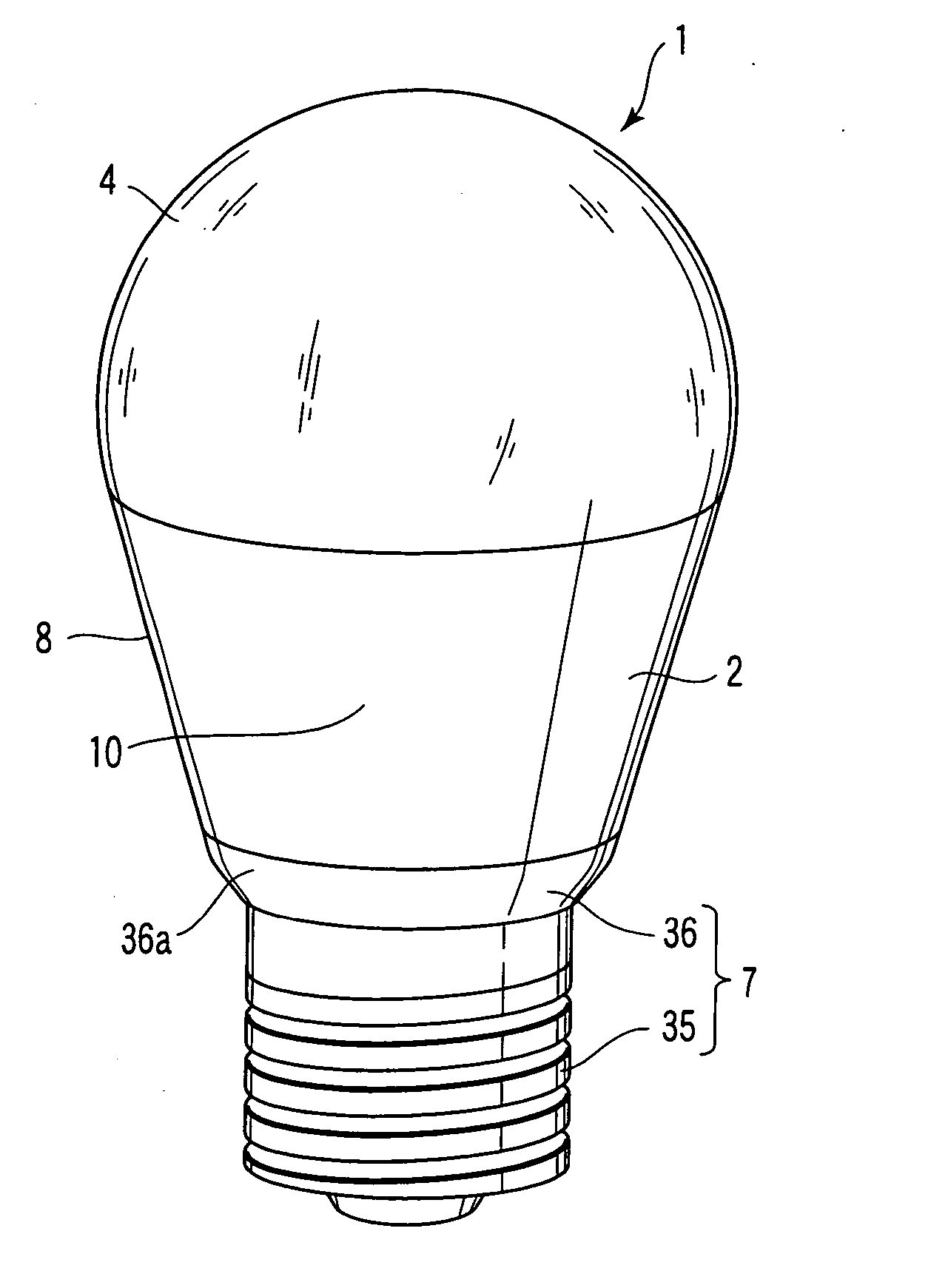
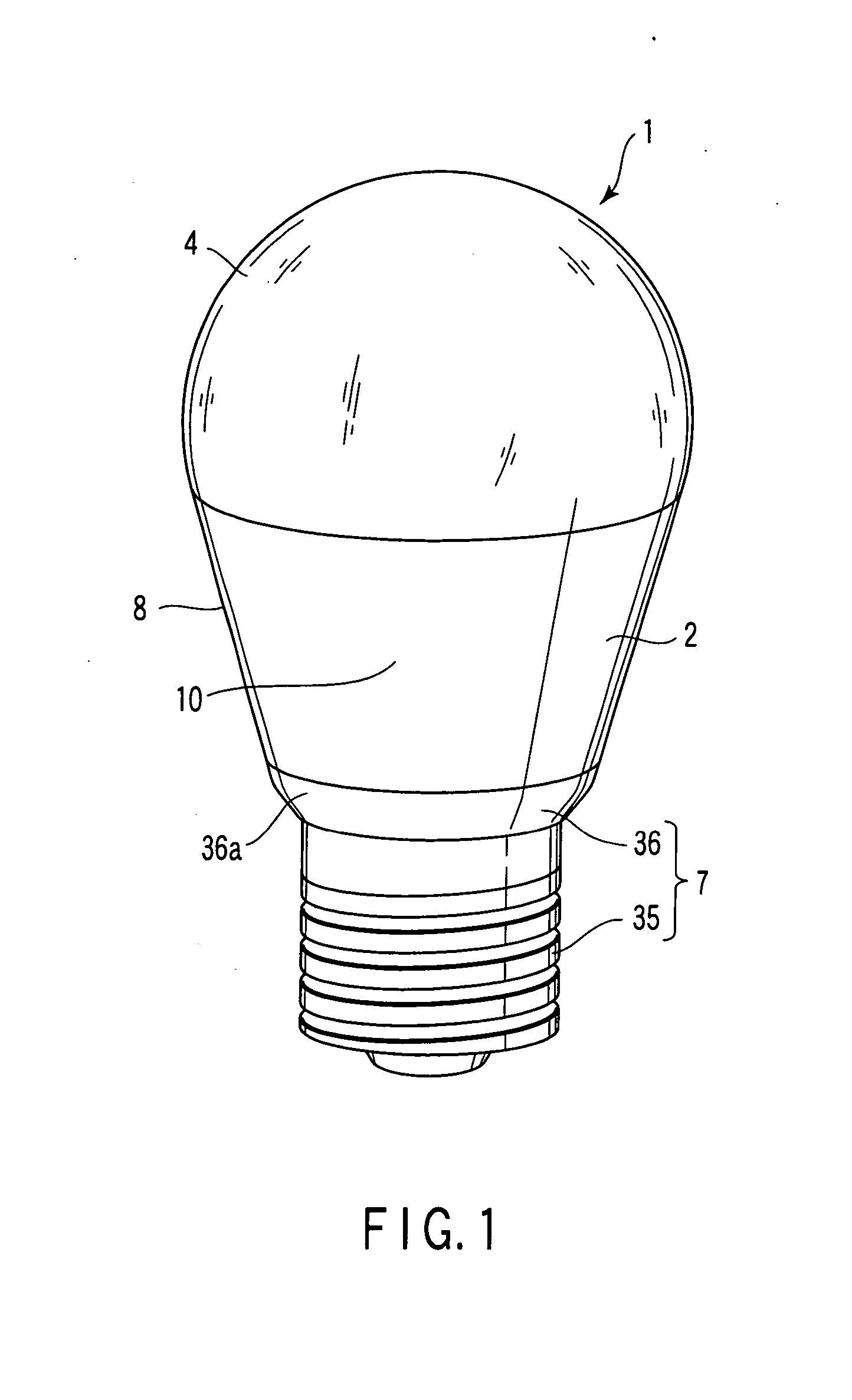
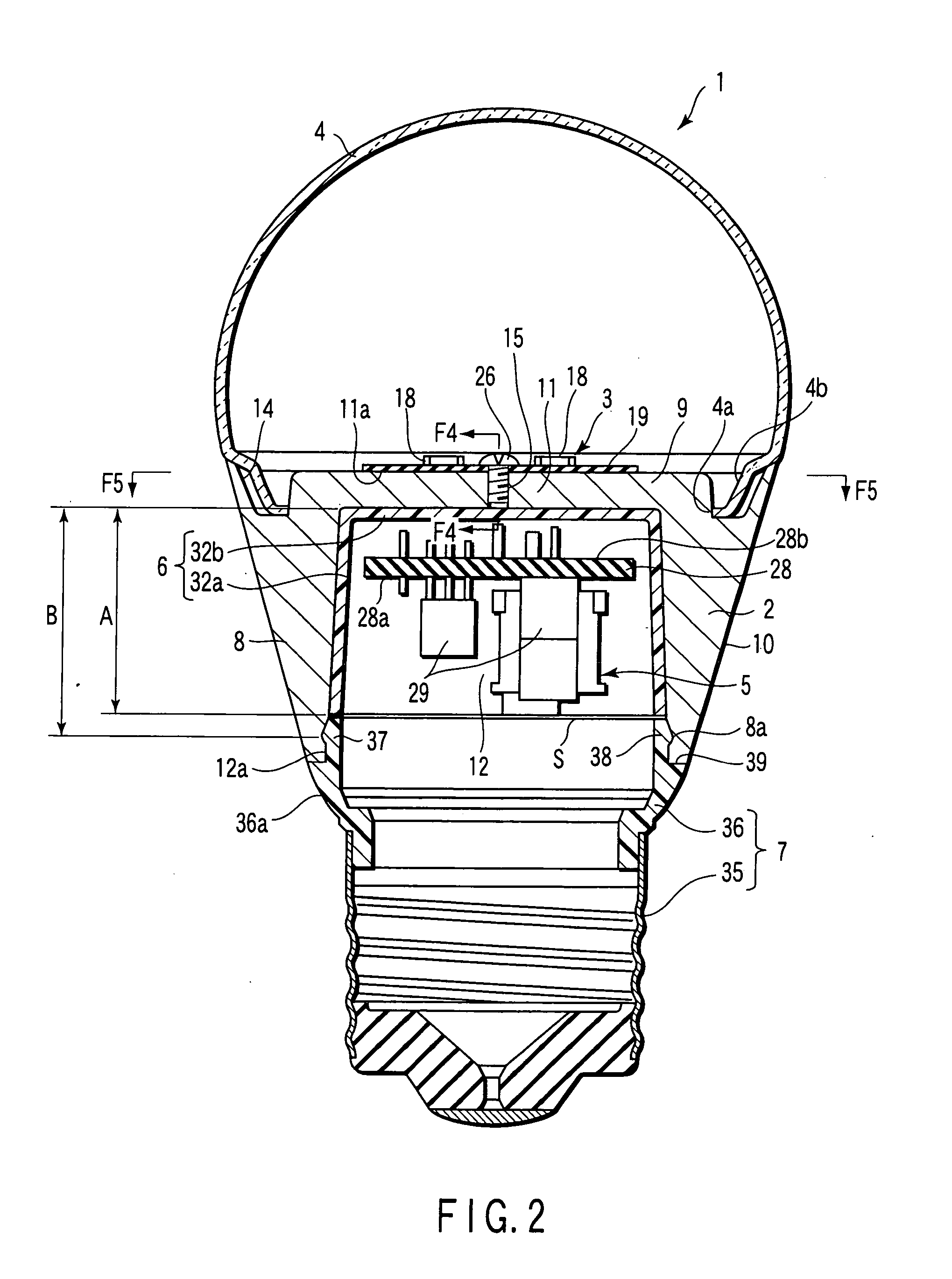
[0050]FIG. 1 and FIG. 2 show a bulb-type lamp 1 compatible with an incandescent lamp. The lamp 1 includes an outer shell 2, a light source 3, a translucent cover 4, a lighting circuit 5, an insulating member 6, and a base 7.

[0051] The outer shell 2 is made of metallic material such as aluminum with excellent heat conductivity. As shown in FIG. 2 and FIG. 3, the outer shell 2 has a peripheral wall 8 and an end wall 9. The peripheral wall 8 and the end wall 9 are formed integrally. The peripheral wall 8 is cylindrical. The outer circumference of the peripheral wall 8 is a heat radiating surface 10 exposed outside the lamp 1. The heat radiating surface 10 is tapered with the outside diameter decreased gradually from one end to the other end along the axial direction of the peripheral wall 8.

[0052] The end wall 9 closes one end of the peripheral wall 8. The end wall 9 forms a circular plate l...

second embodiment

[0082]FIG. 6 and FIG. 7 show the invention.

[0083] The second embodiment is different from the first embodiment in the outer shell 2 and translucent cover 4. The other components of the lamp 1 and technical effects are the same as those of the first embodiment. Therefore, the same components as those of the first embodiment are given same reference numerals, and explanation of these components will be omitted.

[0084] As shown in FIG. 6 and FIG. 7, in the lamp 1 according to the second embodiment, the outside diameter of the peripheral wall 8 of the outer shell 2 is constant except the end portion adjacent to the open end 12a of the receptacle 12 of the outer shell 2. Therefore, the outer shell 2 is shaped like a straight cylinder.

[0085] A globe as the translucent cover 4 has a reflection portion 41a and a projection portion 41b. The reflection portion 41a has an opening 42a opened to the light source support 11, and an edge 42b defining the opening 42a. The edge 42b is fit in the re...

third embodiment

[0092]FIG. 8 shows the invention.

[0093] The third embodiment is different from the first embodiment in the method of fixing the translucent cover 4 to the outer shell 2. The other components of the lamp 1 and technical effects are the same as those of the first embodiment. Therefore, the same components as those of the first embodiment are given same reference numerals, and explanation of these components will be omitted.

[0094] As shown in FIG. 8, the edge 4b of the translucent cover 4 is fixed to the recession 14 of the outer shell 2 through a silicon-based adhesive 51. The adhesive 51 is filled in the recession 14. The recession 14 is formed surrounding the light source support 11, and caved in toward the base 7 from the supporting surface 11a to fix the wiring board 19. Therefore, the adhesive 51 is provided at the position displaced to the base 7 from the light-emitting diodes 18 on the wiring board 19.

[0095] According to the lamp 1 of the third embodiment, the adhesive 51 to ...


PUM


Abstract

A lamp includes an outer shell having heat conductivity, a base provided in the outer shell, and a cover provided in the outer shell. The outer shell has a light source support, and a heat radiating surface exposed to the outside of the outer shell. The light source support is formed integral with the heat radiating surface. A light source is supported on the light source support. The light source is heated during lighting, and thermally connected to the light source support. The light source is covered with the cover.

Description

CROSS-REFERENCE TO RELATED APPLICATIONS [0001] This application is based upon and claims the benefit of priority from prior Japanese Patent Applications No. 2005-112339, filed Apr. 8, 2005, No. 2005-221571, filed Jul. 29, 2005, No. 2005-221688, filed Jul. 29, 2005; and No. 2005-371406, filed Dec. 26, 2005, the entire contents of all of which are incorporated herein by reference. BACKGROUND OF THE INVENTION [0002] 1. Field of the Invention [0003] The present invention relates to a lamp using a semiconductor element like a light-emitting diode as a light source, and more particularly a structure for efficiently radiating the heat generated by a light source during lighting of a lamp. [0004] 2. Description of the Related Art [0005] A light-emitting diode is well known as a light source for a lamp compatible with an incandescent lamp. The output of the light-emitting diode is lowered and the life is reduced, as the temperature is increased. Therefore, it is necessary to control the incr...

Claims


Application Information

Patent Timeline
IPC IPC(8): F21V11/00H05B44/00
CPCF21K9/135F21V29/83F21V3/00F21Y2101/02H05B33/0803F21K9/1375F21V17/101F21V23/002F21V23/006F21V29/004Y02B20/383F21V29/22F21V9/08F21V15/011F21V29/2231F21V29/2293F21V29/507F21V29/70F21V29/773F21K9/1355F21K9/23F21K9/232F21Y2115/10F21K9/238H05B45/30F21V29/89Y02B20/30F21V29/713
Inventor OSAWA, SHIGERUMORIKAWA, KAZUTO
Owner TOSHIBA LIGHTING & TECH CORP
Why Eureka
Try Eureka