Intravascular catheter

a catheter and intravascular technology, applied in the field of medical devices, can solve the problems of long convalescence period, surgeons may have greater difficulty in guiding the guide wire through the occluded area, and dangerous open chest surgery, and achieve the effect of simple construction and convenient us

Inactive Publication Date: 2006-10-12
LEE DON W
View PDF0 Cites 55 Cited by
  • Summary
  • Abstract
  • Description
  • Claims
  • Application Information

AI Technical Summary

Benefits of technology

[0021] An object of the present invention is to provide an intravascular catheter system that can be used in the effective treatment of occluded arteries. More particularly, it is an object of the invention to provide such a system which includes an intravascular catheter that can be easily and safely navigated through severely occluded arteries.
[0025] Another object of the invention is to provide an intravascular catheter system of the class described which is of a simple construction and is easy to use in a conventional manner.

Problems solved by technology

While bypass surgery can provide dramatic relief, it involves dangerous open chest surgery and typically a long period of convalescence.
In those instances where the artery is occluded, the surgeon may have greater difficulty in guiding the guide wire through the occluded area.
Thus, without some type of guidance system, the guide wire might undesirably impinge on and possibly perforate or otherwise damage the artery wall.
However, bi-plane fluoroscopy has been proven to be somewhat costly, unreliable and slow.
The reflections and back-scattered light are combined at an optic coupler, and if the path lengths of the two arms are within the coherence length of the light, the light will recorrelate or interfere with one another.
A drawback found in certain of the prior art OCR optical fiber guide wire systems resides in the fact that the optical fiber guide wire tends to be substantially more difficult to navigate through the artery passageway than the catheters embodying more conventional metal guide wires such as are used in stent delivery and like procedures.

Method used


Image

  • Intravascular catheter
  • Intravascular catheter
  • Intravascular catheter

Examples


Embodiment Construction

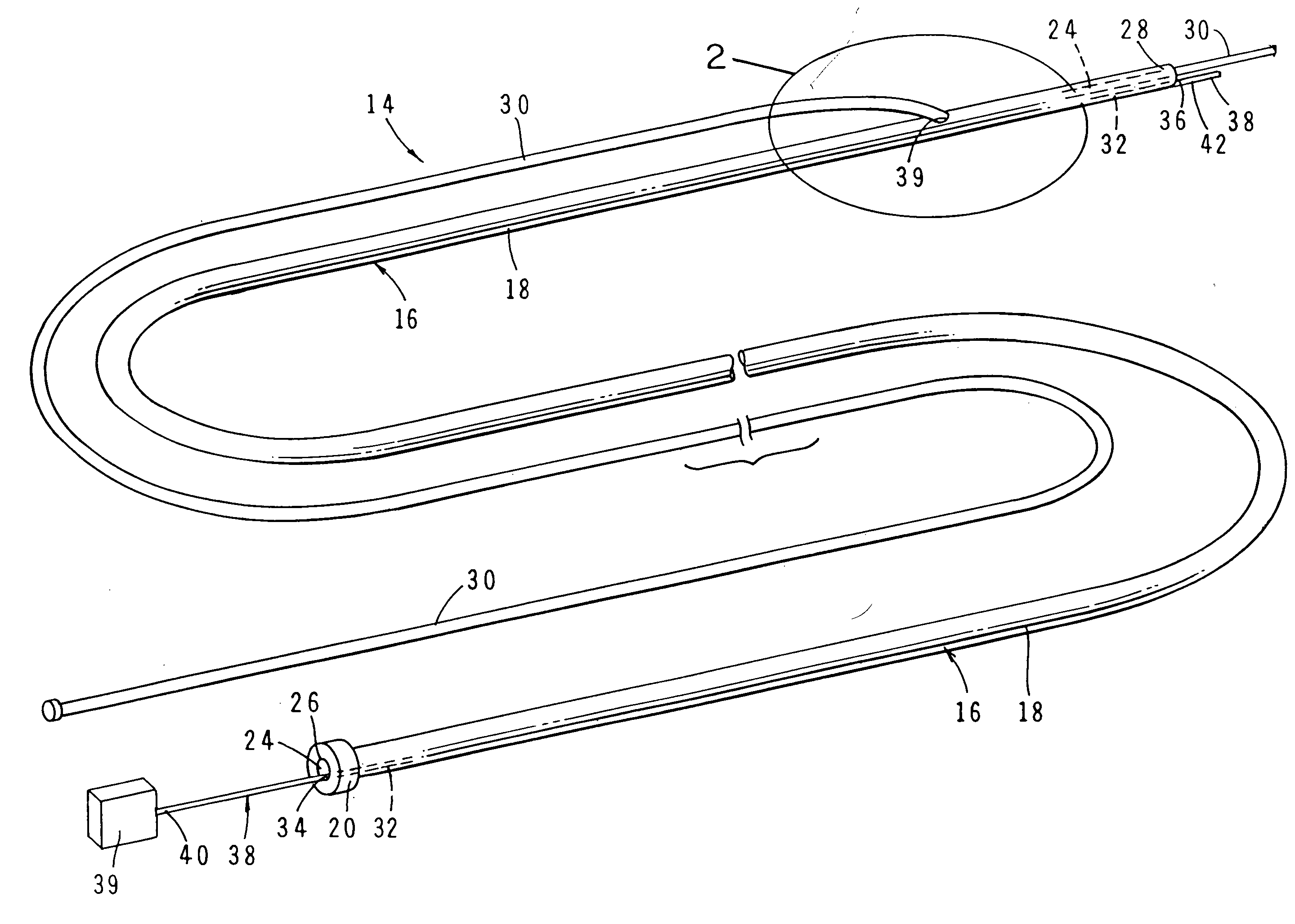
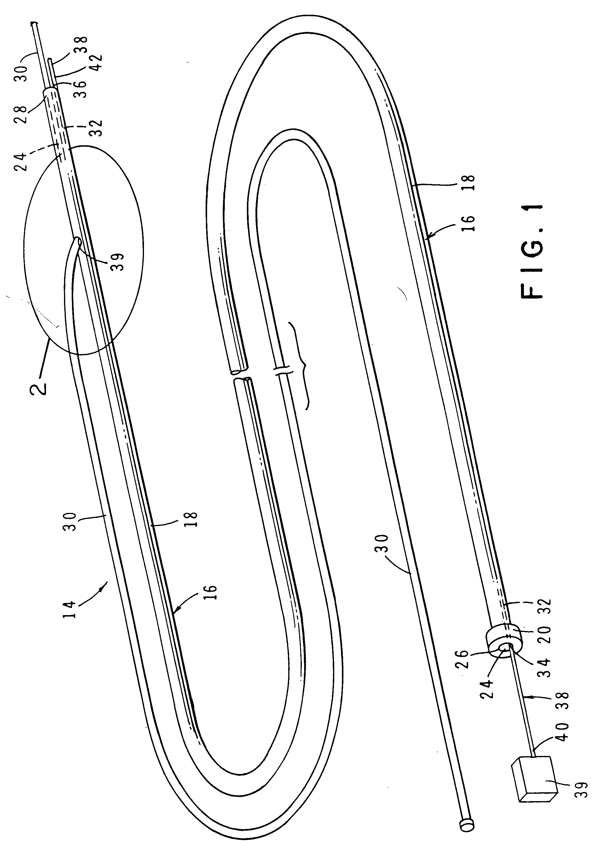
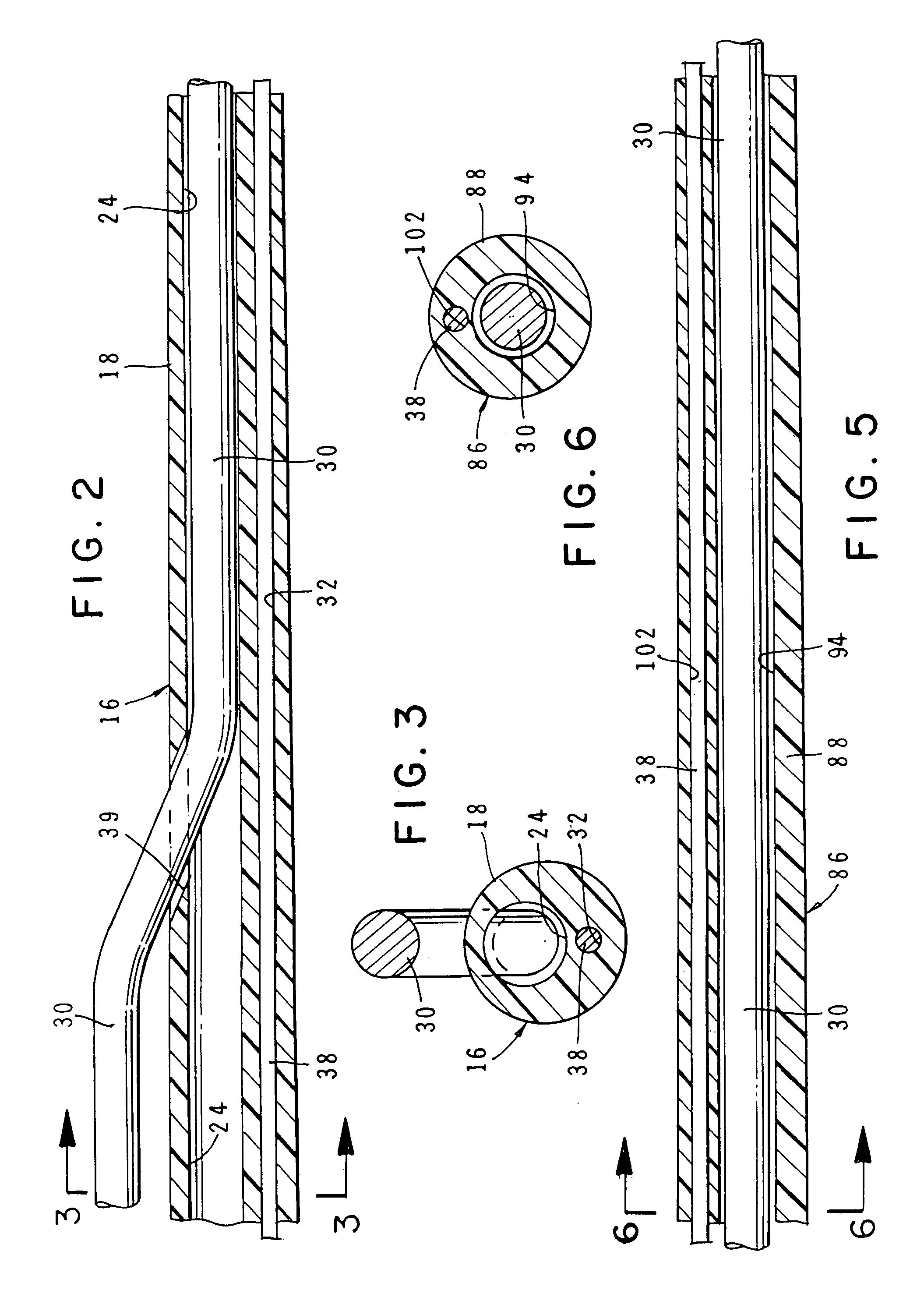
[0040] Referring to the drawings and particularly to FIGS. 1 through 3, one form of the intravascular catheter system of the invention is there shown and generally designated by the numeral 14. The catheter system here comprises a catheter 16 having an outer side wall 18, a proximal end 20 and distal end 22. As can be seen by referring to FIGS. 2 and 3, catheter 16 is provided with a first passageway 24 (FIG. 2) having a diameter of about 0.035 inches, a proximal end 26 and a distal end 28. Catheter 16 is preferably formed of a biocompatible and hydrophilic compatible material, such as a lubricous polyimide or polyethylene.

[0041] As indicated in FIG. 2, a conventional steerable guide wire 30 is slideably receivable within the first passageway 24 and is movable between first and second positions. While various types of steerable guide wires can be used in the catheter assembly of the invention, guide wire 30 is preferably constructed from a flexible, wire-like metal member having a ...


PUM


Abstract

An intravascular catheter system includes an intravascular catheter that can be easily and safely navigated through severely occluded arteries. The system uniquely includes both an optical fiber for use in providing data for guiding the catheter and a conventional metal guide wire for use in navigating the catheter through the artery passageway. The system further includes optical imaging of the arterial occlusion during guidance of the catheter through the artery passageway. More particularly the system provides a visual indication to the surgeon to determine if the catheter assembly is approaching the arterial wall.

Description

[0001] This is a Divisional of co-Pending U.S. Ser. No. 10 / 759,668 filed Jan. 16, 2004.BACKGROUND OF THE INVENTION [0002] 1. Field of the Invention [0003] The present invention relates generally to medical devices such as intravascular catheters. More particularly, the invention concerns an intravascular catheter for use in opening partial and total occlusions of an artery passageway. [0004] 2. Discussion of the Prior Art [0005] A number of procedures have been suggested in the past for treating disease conditions involving the narrowing or obstruction of the lumen of an artery. This condition, generally referred to as an occlusion, is found in patients suffering from atherosclerosis. An occlusion can manifest itself in hypertension and can be partial or total. The occlusions can be found at various locations in the arterial system, including the aorta, the coronary arteries, the carotid arteries and the peripheral arteries. [0006] In the past, coronary artery occlusions have tradit...

Claims


Application Information

Patent Timeline
Patent Type & Authority Applications(United States)
IPC IPC(8): A61B17/00A61B17/22A61B19/00
CPCA61B17/22A61B2017/00057A61B2019/5217A61B2017/22041A61B2017/22074A61B2017/22039A61B2090/3614
Inventor LEE, DON W.
Owner LEE DON W
Why Eureka
Try Eureka