Tissue fixation system and method

a tissue fixation and tissue technology, applied in the direction of prosthesis, ligaments, surgical forceps, etc., can solve the problems of inability to percutaneously perform surgery, bone screws may lose their grip and strip out of bone, side of cortex fixation, etc., to achieve the effect of maintaining tension in the elongated fastening member

Active Publication Date: 2006-10-12
P TECH
View PDF191 Cites 255 Cited by
  • Summary
  • Abstract
  • Description
  • Claims
  • Application Information

AI Technical Summary

Benefits of technology

[0009] The present invention relates to a tissue fixation system. The system comprises an elongate fastening member and a fastener moveable with respect to the elongate fastening member from a first orientation to a second orientation, the fastener having a body with a tissue contacting surface that includes a groove configured and dimensioned to receive a portion of the elongate member in the first orientation. The system can also include a second fastener or other means for maintaining tension in the elongate fastening member.

Problems solved by technology

However, inserting screws through or around fractures can be complex and time-consuming.
In addition to the length and complexity of the process, bone screws also may lose their grip and strip out of the bone.
In addition, currently available lag screws also typically provide only one side of cortex fixation and are generally not suited for percutaneous surgery.
Moreover, when placing the screws in the bone, the physician may not accurately set the screw into the distal hole or may miss the distal hole completely, thereby resulting in the screw stripping the threads or breaking the bone.

Method used


Image

  • Tissue fixation system and method
  • Tissue fixation system and method
  • Tissue fixation system and method

Examples


Embodiment Construction

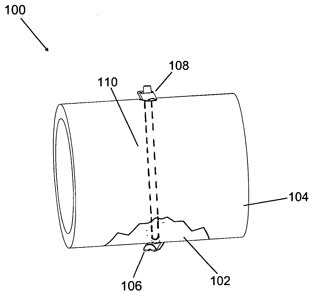
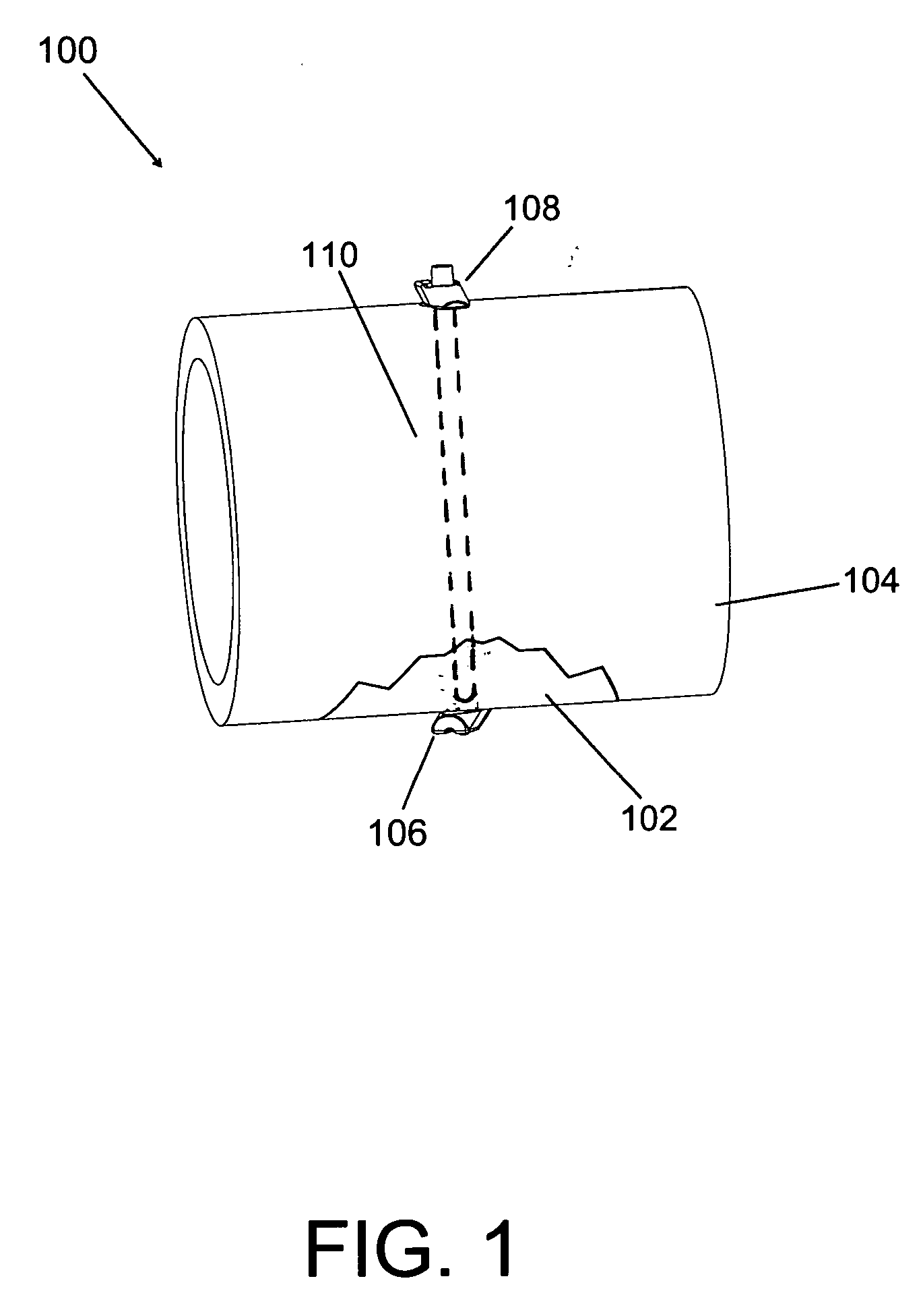
[0061] The present invention provides a tissue fixation system for dynamic and rigid fixation of tissue. The system can be utilized for the fixation and stabilization of body tissue, including soft tissue to soft tissue, soft tissue to bone, and bone to bone. The surgical system can additionally be used to affix implants and grafts to body tissue. The system can access and treat fractured, incised or torn tissue, or the like, from one access area (i.e., from only one opening to the tissue to be fastened) instead of requiring two or more openings. That is, the system is a linear fixation system that can be used with a single, small incision or portal in the skin or other soft tissue to gain access to the fractured bone. The fixation system may be an all-in-one system, packaged as a system kit, for creating a passage in tissue, positioning fasteners, and tensioning an elongate fastening member, like a suture, thread, cable, wire, rod, or pin. The individual components of the system ca...


PUM

PropertyMeasurementUnit
tensionaaaaaaaaaa
adhesiveaaaaaaaaaa
forceaaaaaaaaaa

Abstract

A tissue fixation system is provided for dynamic and rigid fixation of tissue. A fastener connected with an elongate fastening member, such as a cable, wire, suture, rod, or tube, is moved through a passage between opposite sides of tissue. The fastener is provided with a groove that accommodates at least a portion of the fastening member to reduce the profile during the movement through the passage. The fastener is then pivoted to change its orientation. A second fastener can then be connected with the fastening member. While tension is maintained in the fastening member, the fasteners are secured against relative movement. This may be done by deforming the fastening member, either the first or second fasteners, or a bushing placed against the second fastener.

Description

CROSS-REFERENCE TO RELATED APPLICATION [0001] This Application claims the benefit of U.S. Provisional Patent Application No. 60 / 655,140, filed Feb. 22, 2005, entitled TISSUE FIXATION SYSTEM AND METHOD, the content of which is incorporated by reference in its entirety.FIELD OF THE INVENTION [0002] The invention relates to a system and method for fixation and stabilization of tissue. In particular, the invention relates to minimally invasive bone fracture fixation and stabilization. BACKGROUND OF THE INVENTION [0003] It is well-known in the medical arts that applying pressure to tissue helps during the healing process. Incised or torn soft tissue, for example, may be approximated with bandages, sutures, or staples. Proper and more rapid healing of broken or fractured bones likewise may be facilitated by applying constant pressure to the bone. For instance, physicians may insert pins, screws, or bolts in the area of the fracture in order to apply pressure to the fracture. [0004] Howeve...

Claims


Application Information

Patent Timeline
Patent Type & Authority Applications(United States)
IPC IPC(8): A61B17/56
CPCA61B17/0218A61F2310/00293A61B17/1615A61B17/683A61B17/7053A61B17/842A61B17/8869A61B2017/0409A61B2017/2926A61F2/08A61F2/28A61F2/442A61F2002/2817A61F2002/30062A61F2002/30677A61F2002/4435A61F2002/444A61F2210/0004A61B17/0469A61B17/0401A61B17/0467A61B17/0487A61B17/82A61B17/8861A61B17/8863A61B2017/0414A61B2017/0417A61B2017/0458A61B2017/0488A61B2017/0496A61B2017/06176A61B90/40A61B2090/035A61B2090/064A61B17/685A61B17/844
Inventor BONUTTI, PETER M.PHILLIPS, GLEN A.CRAINICH, LARRY
Owner P TECH
Why Eureka
Try Eureka