

Air injector system apparatus and methods for a tub or spa
a technology of air injectors and tubs, which is applied in the direction of baths, douches, physical therapy, etc., can solve the problems of increasing labor and costs, and reducing labor and costs
- Summary
- Abstract
- Description
- Claims
- Application Information
AI Technical Summary
Benefits of technology
Problems solved by technology
Method used
Image

Examples
Embodiment Construction
, Drawings, and the Claims appended herewith.
SUMMARY OF THE INVENTION
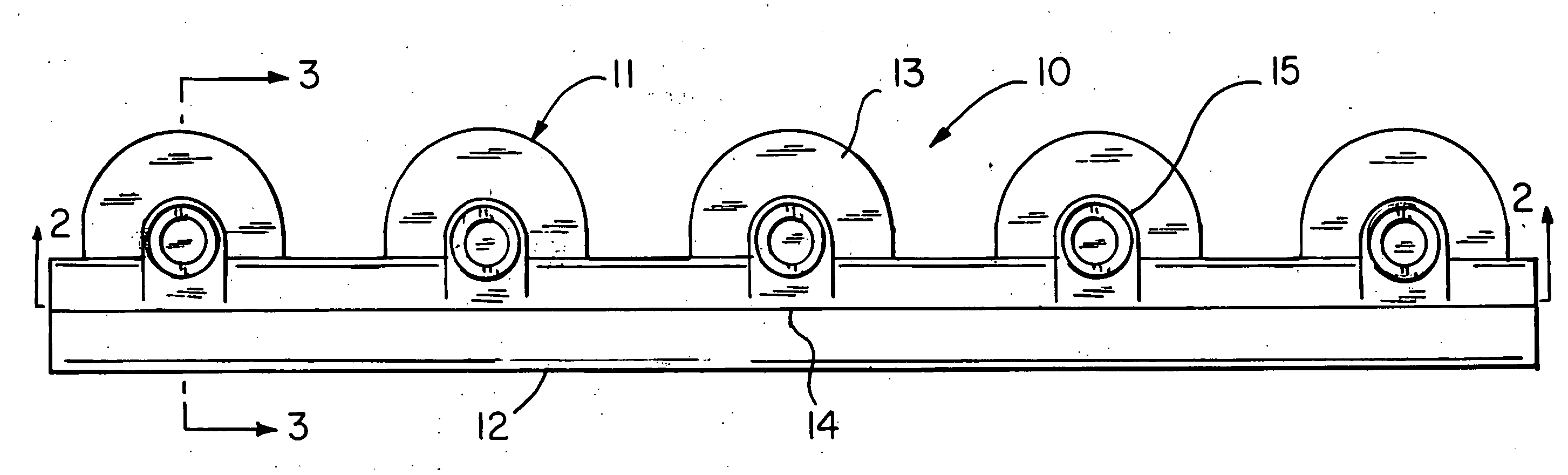
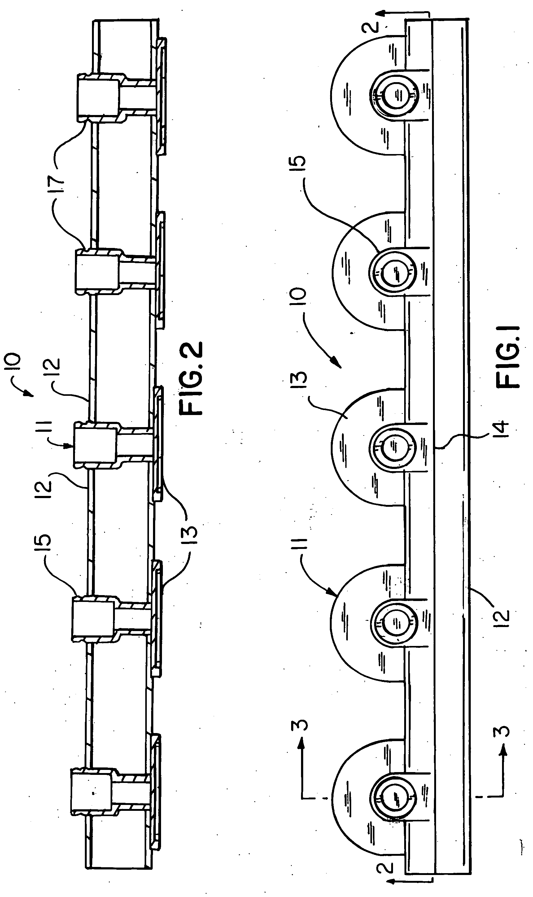
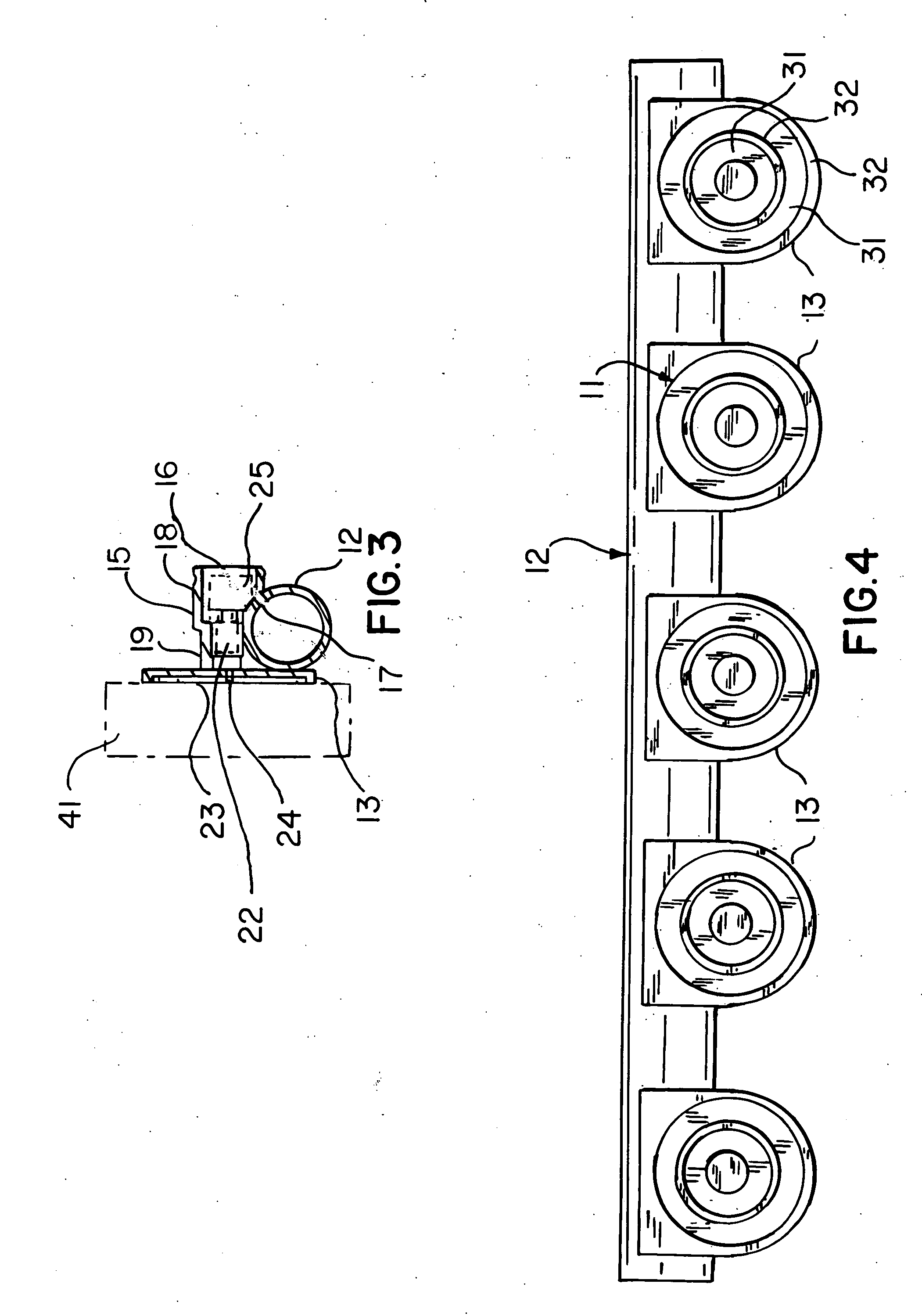
[0012] The present invention accomplishes the above-stated objective as well as others, as may be determined by a fair reading and interpretation of the entire specification herein. The present invention comprises an integral array of a plurality of air injector nozzles connected to a common air flow communication member. Each individual nozzle comprising a combination including an air flow tube, an air injector flow tube, and an attaching member. The air flow tube of each air injector nozzle in practice comprises a portion of the air flow communication member. The array of injector nozzles provides for correct alignment between individual nozzles when attached to a tub. Provides for even distribution of the individual nozzles on the tub. Provides a means for selectively configuring the proper number of nozzles regardless of the size of the tub and the desired arrangement of the nozzles on the tub. Provides for ut...
PUM
 Abstract
Description
Claims
Application Information