Dust-separating apparatus for vacuum cleaner

a technology of dust separation apparatus and vacuum cleaner, which is applied in the field of vacuum cleaner, can solve the problems of increasing pressure loss and deteriorating an initial suction force, and achieve the effect of improving dust separation efficiency and reducing pressure loss

Inactive Publication Date: 2006-10-19
SAMSUNG GWANGJU ELECTRONICS CO LTD
View PDF4 Cites 19 Cited by
  • Summary
  • Abstract
  • Description
  • Claims
  • Application Information

AI Technical Summary

Benefits of technology

[0011] An aspect of the present invention is to solve at least the above problems and/or disadvantages and to provide at least the advantages described below. Accordingly, an aspect of the present inventio...

Problems solved by technology

However, in the multi-cyclone dust separating apparatus, an air path is formed long and a course of...

Method used


Image

  • Dust-separating apparatus for vacuum cleaner
  • Dust-separating apparatus for vacuum cleaner
  • Dust-separating apparatus for vacuum cleaner

Examples


Embodiment Construction

[0023] Hereinafter, an embodiment of the present invention will be described in detail with reference to the accompanying drawing figures.

[0024] In the following description, same drawing reference numerals are used for the same elements even in different drawings. The matters defined in the description such as a detailed construction and elements are nothing but the ones provided to assist in a comprehensive understanding of the invention. Thus, it is apparent that the present invention can be carried out without those defined matters. Also, well-known functions or constructions are not described in detail since they would obscure the invention in unnecessary detail.

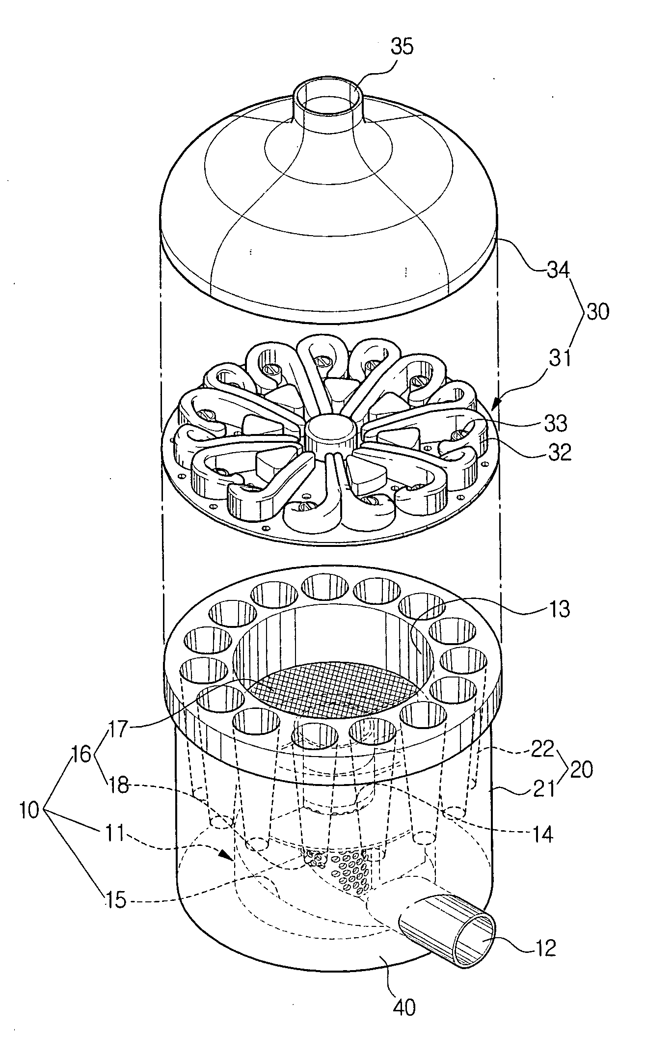
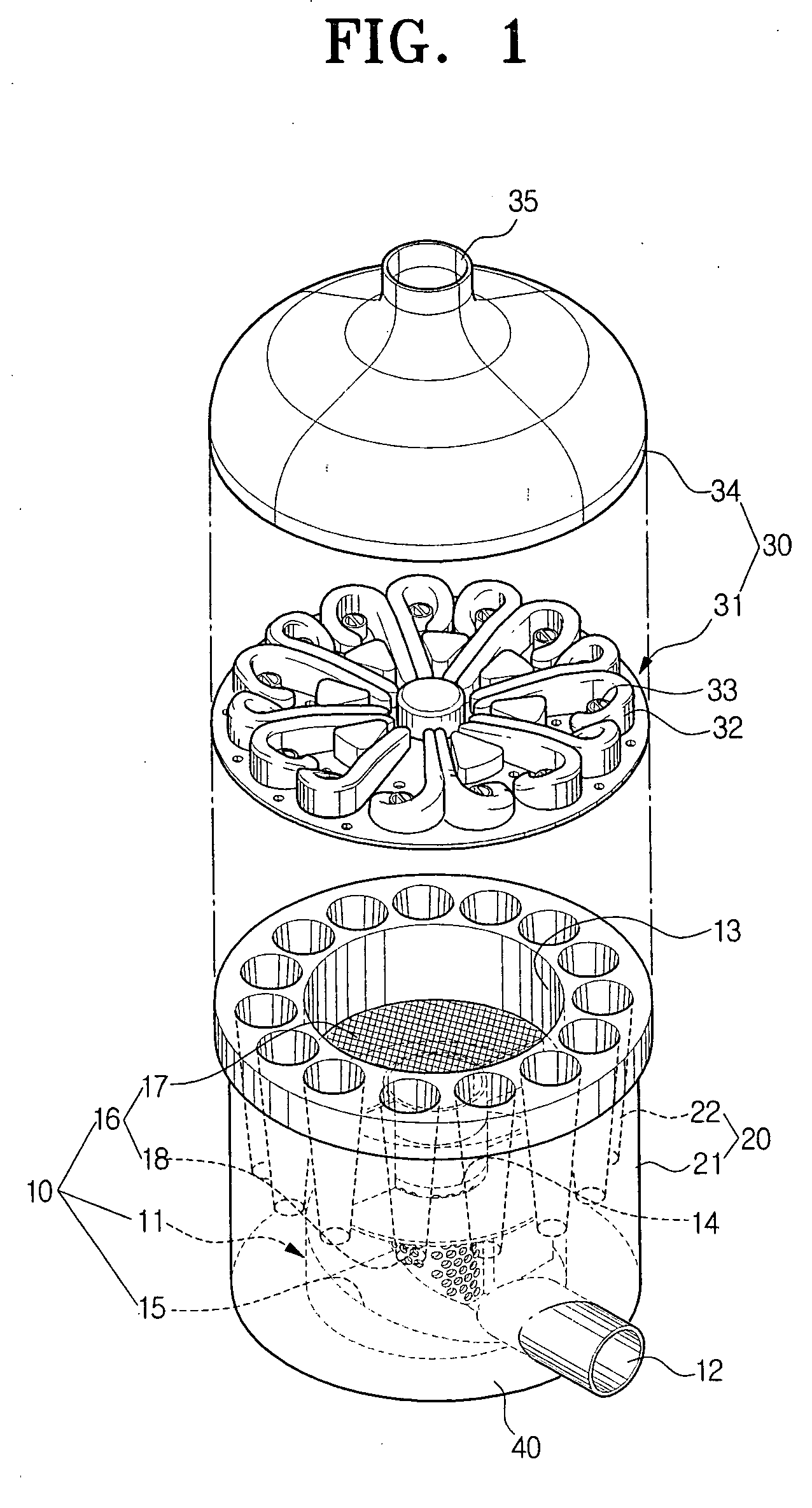
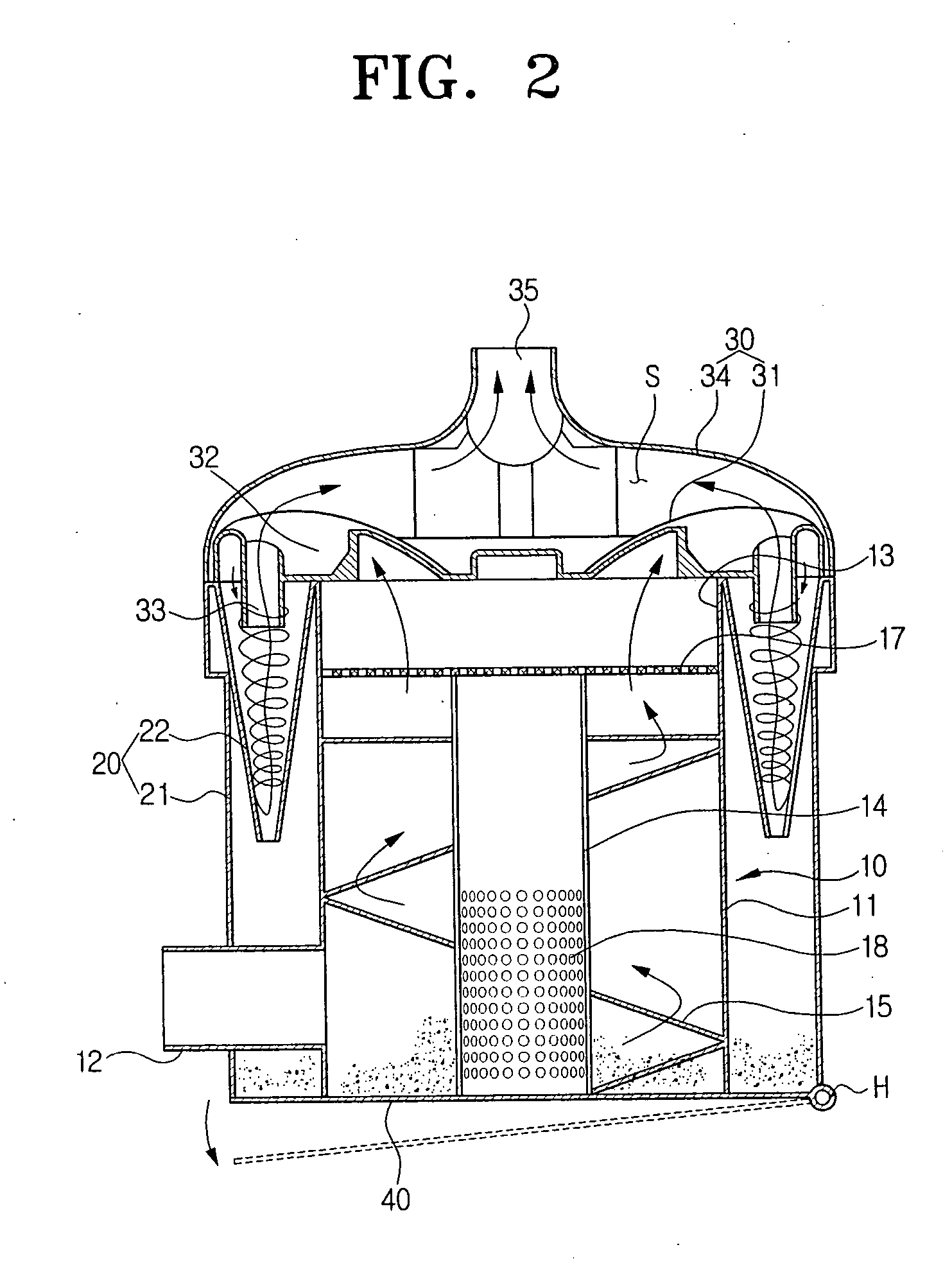
[0025] As shown in FIGS. 1 and 2, a dust separating apparatus for a vacuum cleaner, according to an embodiment of the present invention is shown. The dust separating apparatus comprises first and second dust separating units 10 and 20, and a cover unit 30.

[0026] The first dust separating unit 10 separates relatively ...


PUM

PropertyMeasurementUnit
Depthaaaaaaaaaa

Abstract

A dust separating apparatus for a vacuum cleaner is provided. The dust separating apparatus comprises a first dust separating unit having a suction port, a guide member spirally, and a main filter to collect dust separated from drawn-in air, a second dust separating unit including a plurality of cyclones annularly arranged to centrifugally separate the dust from the air discharged from the first dust separating unit, and a cover unit to guide the air discharged from the first and the second dust separating units. The first dust separating unit separates the dust included in drawn-in air by rotating along the guide member and passing through the main filter the air drawn in through the suction port. The second dust separating unit rotates the air discharged from the first dust separating unit, thereby further filtering the air.

Description

CROSS-REFERENCE TO RELATED APPLICATIONS [0001] This application claims benefit under 35 U.S.C. § 119(e) of U.S. Provisional Application No. 60 / 666,302 filed on Mar. 29, 2005 in the United States Patent and Trademark Office, and benefit under 35 U.S.C. § 119(a) of Korean Patent Application No. 2005-38289 filed on May 9, 2005 in the Korean Intellectual Property Office, the entire disclosures of which are incorporated herein by reference.BACKGROUND OF THE INVENTION [0002] 1. Field of the Invention [0003] The present invention relates to a vacuum cleaner. More particularly, the present invention relates to a dust separating apparatus mounted in a vacuum cleaner body to separate and collect dust included in drawn-in air. [0004] 2. Description of the Related Art [0005] General vacuum cleaners comprise a dust separating apparatus which draws in dust-laden air using a suction force generated by a suction motor mounted in a cleaner body and separates dust from the drawn-in air. [0006] Genera...

Claims


Application Information

Patent Timeline
IPC IPC(8): B01D45/12
CPCA47L9/1608A47L9/1625A47L9/1641A47L9/1666B04C2009/002B04C5/185B04C7/00B04C9/00B04C2003/006B01D45/12Y10S55/03A47L9/16A47L9/12
Inventor HAN, JUNG-GYUNOH, JANG-KEUN
Owner SAMSUNG GWANGJU ELECTRONICS CO LTD
Why Eureka
Try Eureka