Electropneumatic paintball gun, method of making and operating, and retrofit kit assembly

a paintball gun and electropneumatic technology, applied in the field of pneumatic marker or paint ball guns, can solve the problems of uncertain engagement and release of mechanical hammer and sear, and achieve the effect of reducing or eliminating at least on

Inactive Publication Date: 2006-10-19
STYLES LEON +1
View PDF4 Cites 11 Cited by
  • Summary
  • Abstract
  • Description
  • Claims
  • Application Information

AI Technical Summary

Problems solved by technology

However, a common problem with the conventional electro-pneumatic paint ball guns is that they use a mechanical sear device to release a hammer.
The adjustment of the engagement and release of the mechanical hammer and sear remains an uncertain element of conventional paint ball gun operation, requiring frequent adjustments in order to operate at high cyclic rates.

Method used


Image

  • Electropneumatic paintball gun, method of making and operating, and retrofit kit assembly
  • Electropneumatic paintball gun, method of making and operating, and retrofit kit assembly
  • Electropneumatic paintball gun, method of making and operating, and retrofit kit assembly

Examples


Embodiment Construction

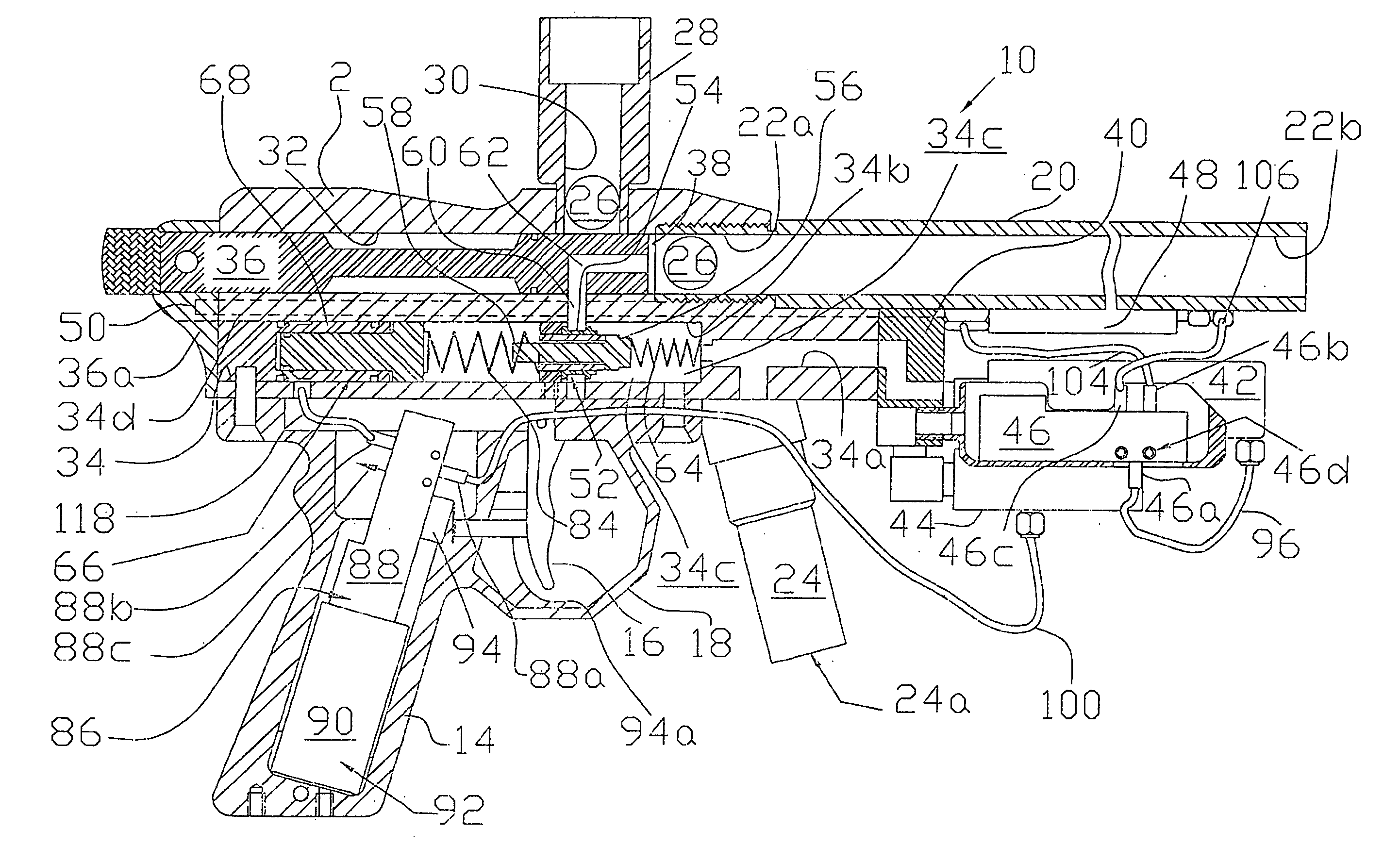
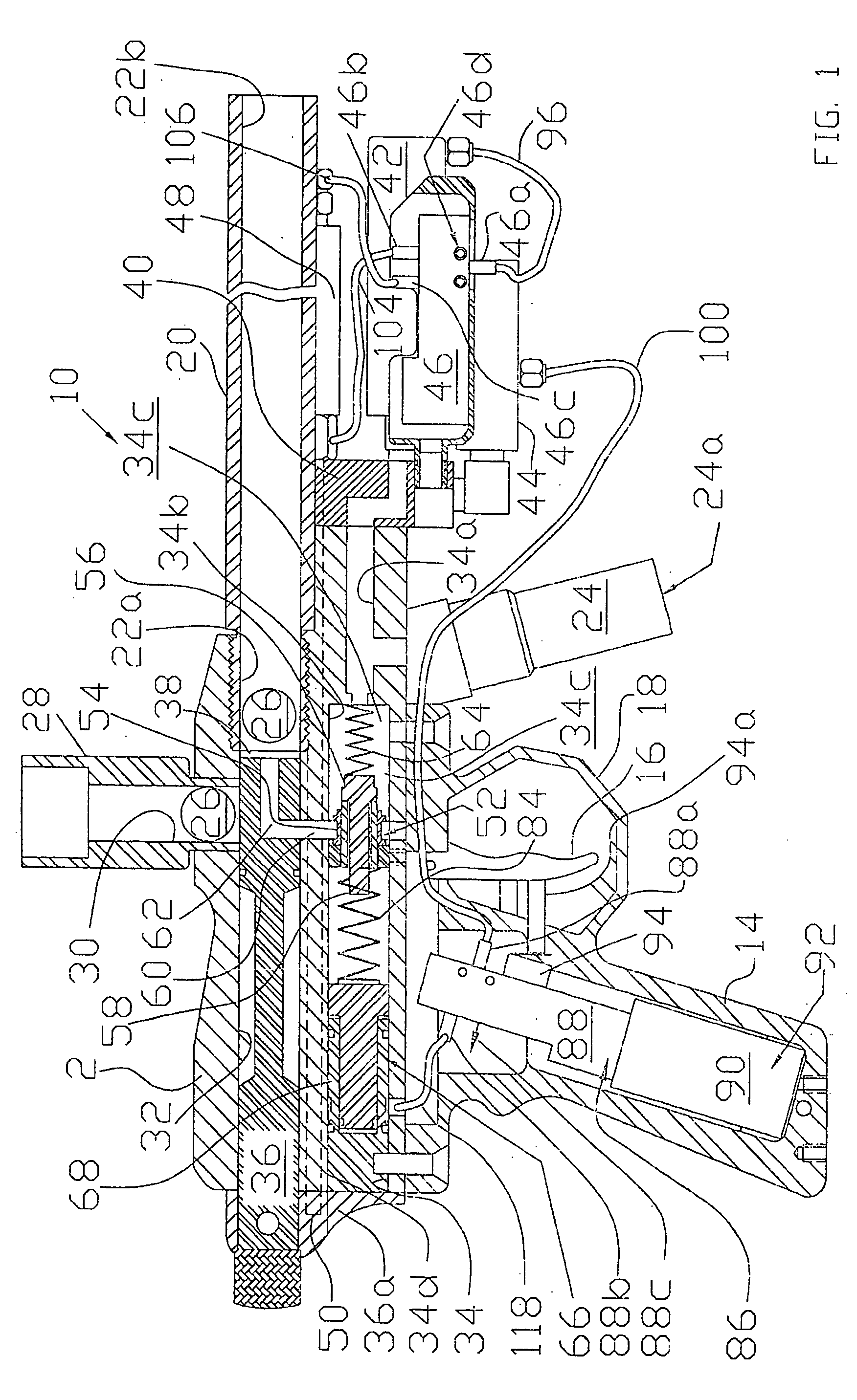
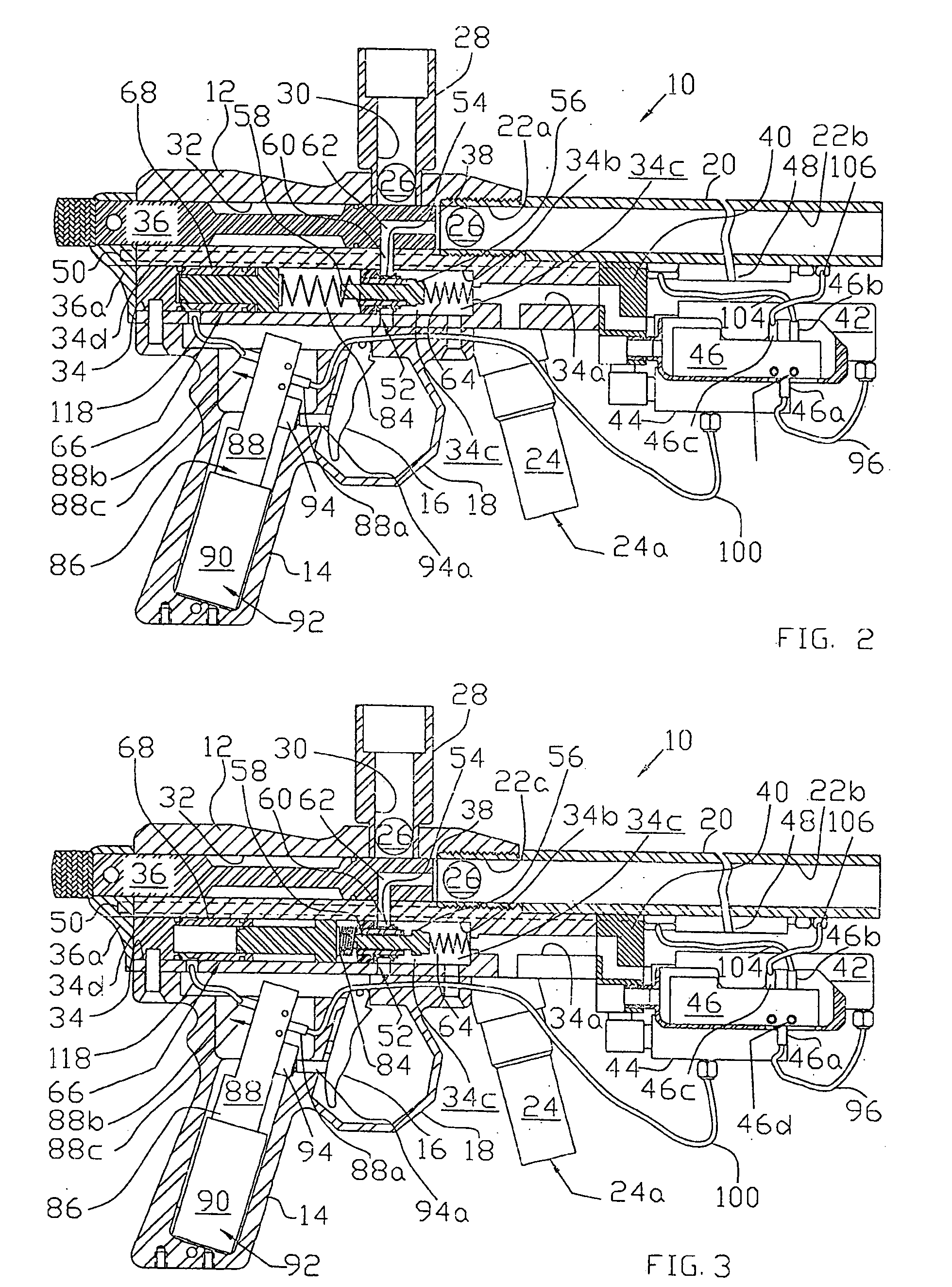
[0020] Referring to the drawing Figures in conjunction with one another, and first considering especially FIG. 1, a paint ball gun 10 includes a main body 12, with a grip frame 14 pivotally carrying a trigger 16 and defining a trigger guard 18. A barrel 20 is attached to the main body 12, and defines a breech opening 22a by which a paint ball is received, and muzzle opening 22b by which a paint ball is discharged. A gas inlet regulator body 24 is also attached to the main body 12, and provides communication via an inlet 24a (arrowed on FIG. 1) with a source of high pressure gas (not shown in the drawing Figures) for powering the paint ball gun 10.

[0021] A paint ball hopper and feeding device (also not seen in the drawing Figures) can be mounted on the top of the main body 12, feeding paintballs 26 into the gun 10 via an upper feed tube 28 defining a feed port 30. The feed port 30 opens into a top one 32 of two substantially parallel and vertically spaced bores (i.e., bores 32 and 3...


PUM


Abstract

An electro-pneumatically operated paint ball gun operates without the use of a mechanical sear, and includes a pneumatically operated hammer assembly effective to bump open a discharge valve and fire the gun. A programmable, microprocessor-based controller allows default values for time intervals of operation of the gun to be programmed, and also allows a user of the gun to access and change default values so that the operation of the gun can be modified to better meet the user's preferences. A cyclic rate of fire of as much as 30 paint ball shots per second or more is possible with a paint ball gun according to this invention. Further, a retrofit kit assembly provides for conversion of a conventional “autococker” type of paint ball gun into a gun embodying the present invention.

Description

FIELD OF THE INVENTION [0001] The invention relates to a pneumatic marker or paint ball gun, to a method of making and operating such a paint ball gun, and to a retrofit kit for converting a conventional paintball gun to embody the improved structure and operation of this invention. BACKGROUND OF THE INVENTION [0002] Paint ball guns were originally developed for marking uses such as forestry and cattle ranching, in which frangible projectiles or paint balls were fired against trees to be harvested or cattle to be taken to market, for example. For this reason, the paint ball guns themselves are frequently referred to as “markers.” But, more recently paint ball guns are much more widely used in various recreational environments, such as simulated war games wherein it is the intent to shoot at an opposing player with the paint ball gun, thus marking this opposing player with a particular color of paint from a frangible paint ball. [0003] Paint ball guns using compressed air or gas for ...

Claims


Application Information

Patent Timeline
Patent Type & Authority Applications(United States)
IPC IPC(8): F41B11/00F41A7/08F41A19/58
CPCF41A7/08F41A19/58F41B11/00F41B11/723F41B11/68F41B11/71F41B11/722F41B11/57F41A19/10F41A19/24
Inventor STYLES, LEONGARDNER, JASON
Owner STYLES LEON
Why Eureka
Try Eureka