
Autofocus device and method

Inactive Publication Date: 2006-10-19
SONY CORP
View PDF3 Cites 10 Cited by
  • Summary
  • Abstract
  • Description
  • Claims
  • Application Information

AI Technical Summary

Benefits of technology

[0006] A video camera used for broadcasting or professional use has lens with a large aperture to fail to wobble briefly and speedy, thereby resulting in spending much time for determining the driving direction of the focus lens.
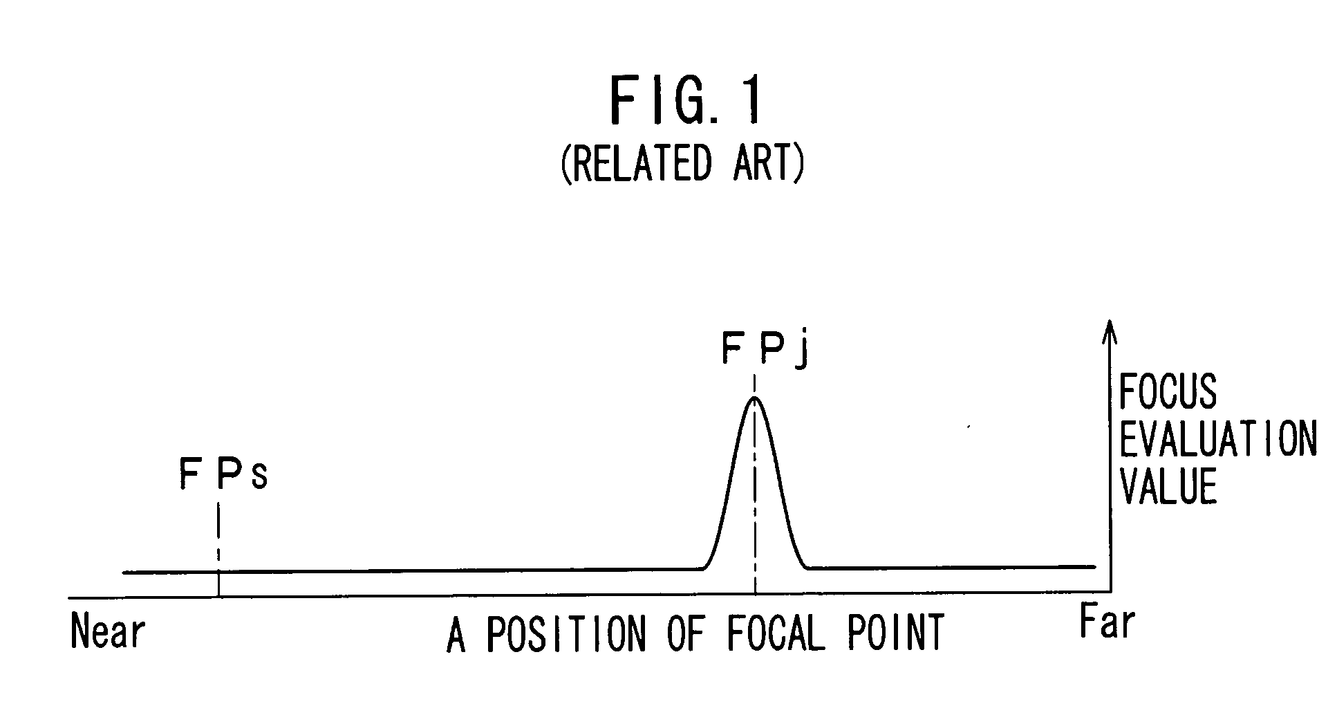
[0009] It is desirable to present autofocus device and method and a program product therefor that can rapidly drive the focus lens to meet the position of the focal point thereof to the in-focus position FPj and get an image without any blurs relative to the subject.
[0019] Thus, according to any embodiments of the invention, the driving direction of the lens and the driving speed of the lens are set on the basis of the detected position of a focal point and the detected distance result and then, the focusing operation to drive the lens to meet a position of its focal point to an in-focus position starts. This start of driving the lens (for example, a focus lens) without any wobbling allows to be shortened a period of time for such the focusing operation, thereby getting an image of subject having no blur rapidly.

Problems solved by technology

A video camera used for broadcasting or professional use has lens with a large aperture to fail to wobble briefly and speedy, thereby resulting in spending much time for determining the driving direction of the focus lens.
As a result thereof, it may be difficult to determine a direction in which the in-focus position FPj stays.
In this condition, even if the wobbling lens wobbles, it may be further difficult to determine a driving direction of the focus lens.
This elongates a period of focusing time for the focus lens to reach the in-focus position FPj, thereby failing to rapidly get an image without any blurs relative to the subject.

Method used


Image

  • Autofocus device and method
  • Autofocus device and method
  • Autofocus device and method

Examples


Embodiment Construction

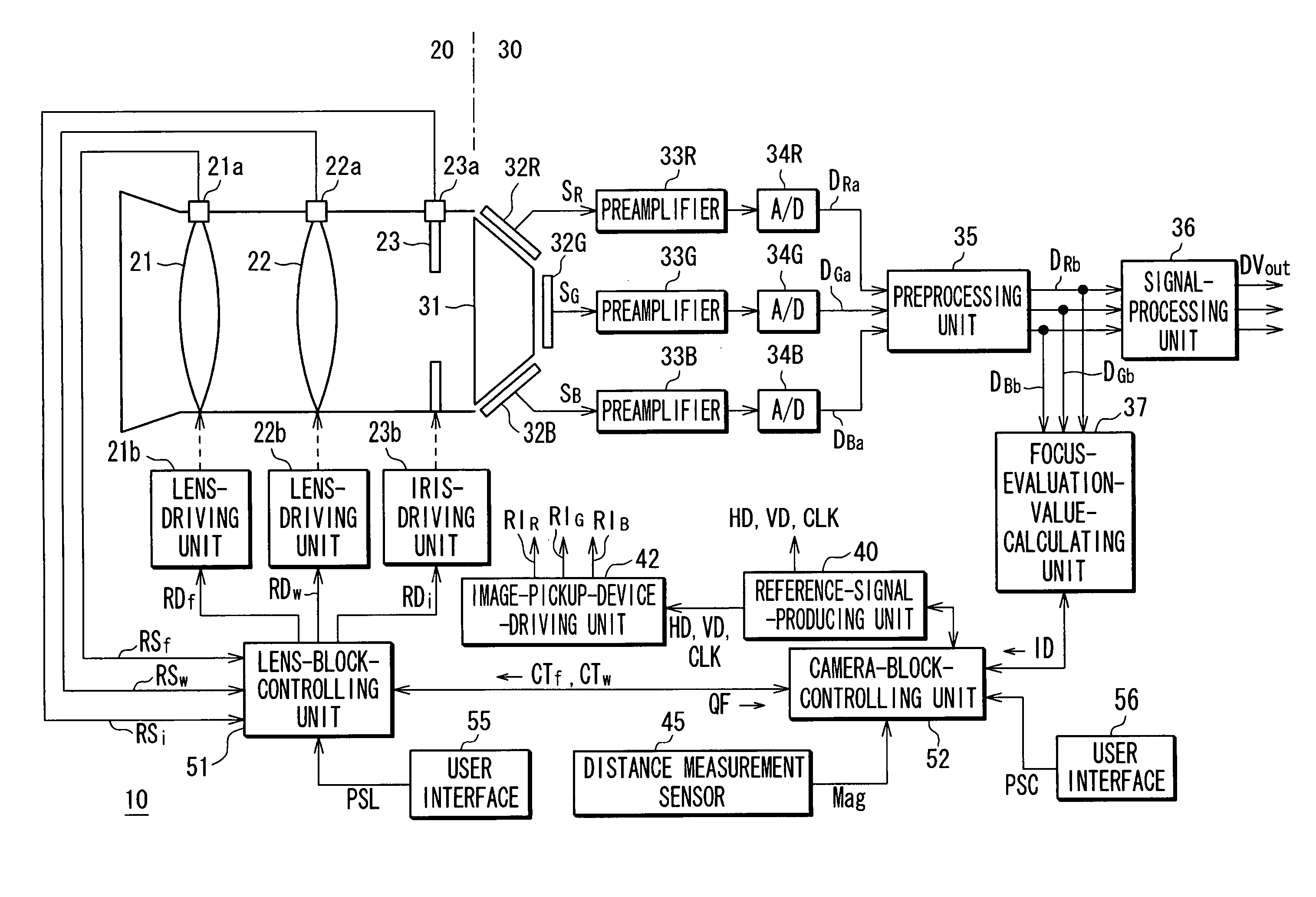
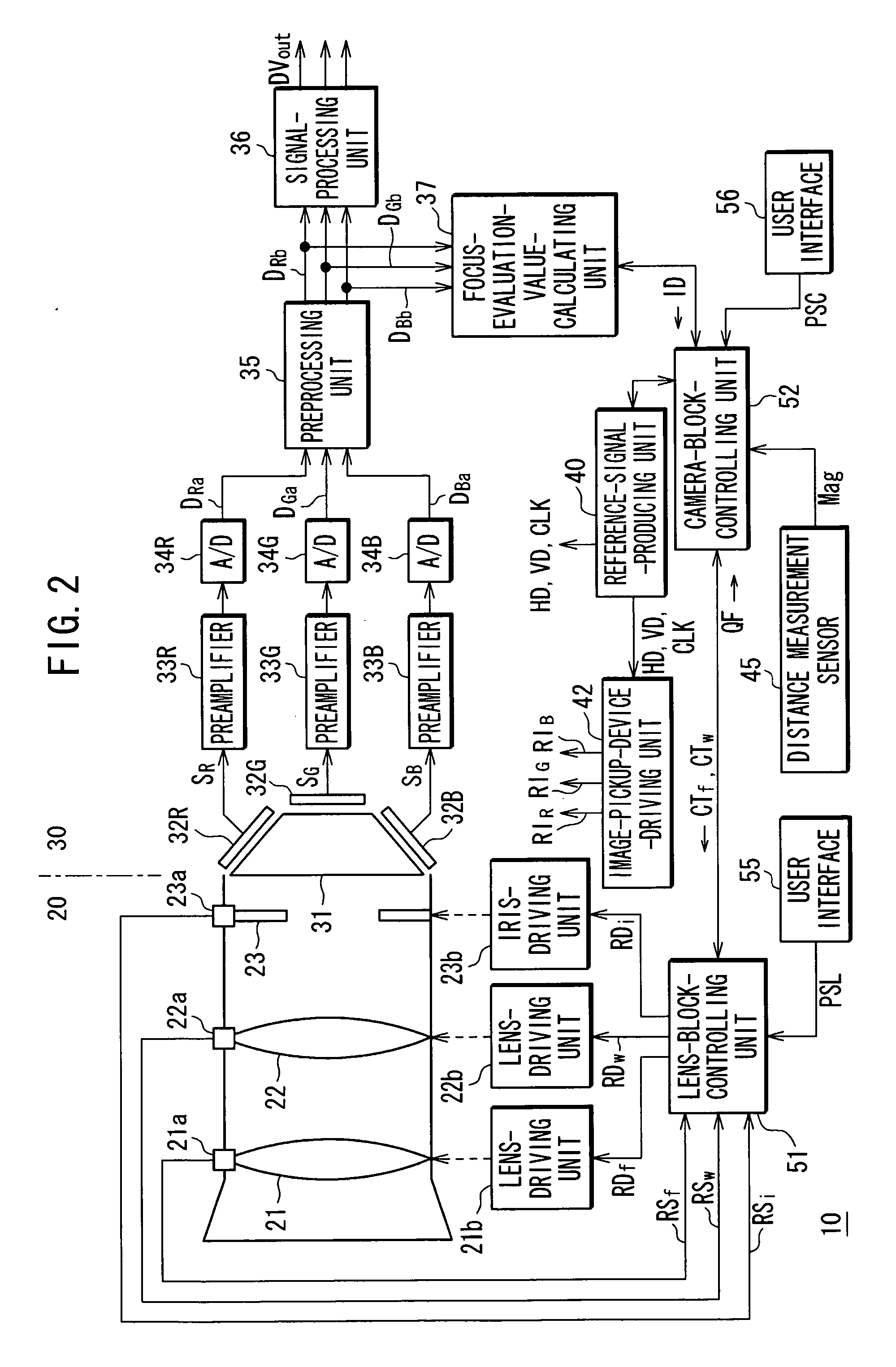
[0031] The following will describe embodiments of the invention with reference to the accompanying drawings. FIG. 2 shows a whole configuration of an imaging apparatus such as a video camera 10 having an autofocus mechanism.

[0032] A lens block 20 of the video camera 10 is constituted of an imaging lens, a lens-position-detecting unit that detects a position of the imaging lens, lens-driving unit that drives the imaging lens and the like. It is to be noted that in the lens block 20 shown in FIG. 2, as the imaging lens, a focus lens 21 for focusing an image of subject on an imaging surface of an imaging element and a wobbling lens 22 for utilizing determination of a driving direction of the focus lens 21 to meet a position of its focal point to an in-focus position are illustrated.

[0033] For the focus lens 21, are provided a lens-position-detecting unit 21a that detects a position of the focus lens 21, i.e. a focal-point-position-detecting unit that detects a position of a focal poi...


PUM


Abstract

Autofocus device has a lens-driving unit that drives a lens and a focal-point-position-detecting unit that detects a position of a focal point of the lens. The device also has a distance-measuring sensor that measures a distance to a subject and a control unit that performs a focusing operation to control the lens-driving unit to drive the lens, thereby meeting the position of the focal point of the lens detected by the focal-point-position-detecting unit to an in-focus position thereof. The control unit allows to be set a driving direction of the lens and a driving speed of the lens based on the position of the focal point of the lens detected by the focal-point-position-detecting unit and a distance measurement result measured by the distance-measuring sensor. The focusing operation then starts.

Description

CROSS REFERENCE TO RELATED APPLICATION [0001] The present invention contains subject matter related to Japanese Patent Application No. JP2005-119034 filed in the Japanese Patent Office on Apr. 15, 2005, the entire contents of which being incorporated herein by reference. BACKGROUND OF THE INVENTION [0002] 1. Field of the Invention [0003] This invention relates to autofocus device and method and a program product therefor, which are used in an imaging apparatus such as a video camera and a digital still camera. [0004] 2. Description of Related Art [0005] The imaging apparatus such as a video camera and a digital still camera has been equipped with any autofocus mechanism that automatically focuses on a subject. The autofocus mechanism adds frequency components of an image signal in a particular region that is provided in an imaging frame (finder's view) to calculate a focus evaluation value thereof and drives a focus lens so that the maximum focus evaluation value can be given (see J...

Claims


Application Information

Patent Timeline
IPC IPC(8): G03B13/00
CPCG02B7/36H04N5/23212G03B13/36H04N23/673G02B7/28
Inventor ITO, YUJIROSUTO, HIDEKAZUTAKEMOTO, SHINJI
Owner SONY CORP
Learn More