Information recording carrier and method of reproducing the same

a technology of information recording carrier and information recording mark, which is applied in the field of information recording carrier, can solve the problems of increasing the error rate of the recording mark in some cases, the capacity of the information recording carrier whose area is limited, and the rate of address drop

Inactive Publication Date: 2006-10-19
JVC KENWOOD CORP
View PDF4 Cites 0 Cited by
  • Summary
  • Abstract
  • Description
  • Claims
  • Application Information

AI Technical Summary

Benefits of technology

[0030] An object of the present invention is to provide an information recording carrier in which the address is buried effectively by referring to such updated technological background.

Problems solved by technology

However, because recording cannot be achieved in this header region, the entire capacity of an information-recording carrier whose area is limited drops.
Consequently, the error rate of address rises so that the error rate of the recording mark may rise in some cases.
When the inventor of the present invention considered this address recording method under various unfavorable conditions, more specifically, recorded user data into the groove 151 in a disc of phase change type created based on this method and tried to reproduce the address, it was found that the recorded user data leaked into the address signal thereby causing a trouble in address detection.
However, in viewpoint of address reproduction, recording user data acted like noise and it was found that detection of the address, more specifically detection of the phase switching point 153 was often mistaken.
Although when the reproduction by envelope phase detection was replaced with the reproduction by synchronous phase detection as its countermeasure, the error rate dropped by about 1 digit, the effect was not sufficient.
In this case, although there was some extent of the effect, interference increased so that the error rate of user recording worsened or in worst case, the tracking became unstable.
This problem is originated from a fact that this address recording method depends on minute change in shape of the phase switching point 153.
Further, under this address recording method, address in adjacent tracks leaked so that it was mixed into main address about once every several tracks.
As a result, not only the phase switching point 153 is difficult to detect, but also this phenomenon reduces the reliability of the information recording carrier remarkably.
Further, although technology for forming the information recording carrier in multiple layers so as to increase its recording capacity has been well known, it must be considered that noise in the reproducing system is increased by this multiple-layers.

Method used


Image

  • Information recording carrier and method of reproducing the same
  • Information recording carrier and method of reproducing the same
  • Information recording carrier and method of reproducing the same

Examples


example 1

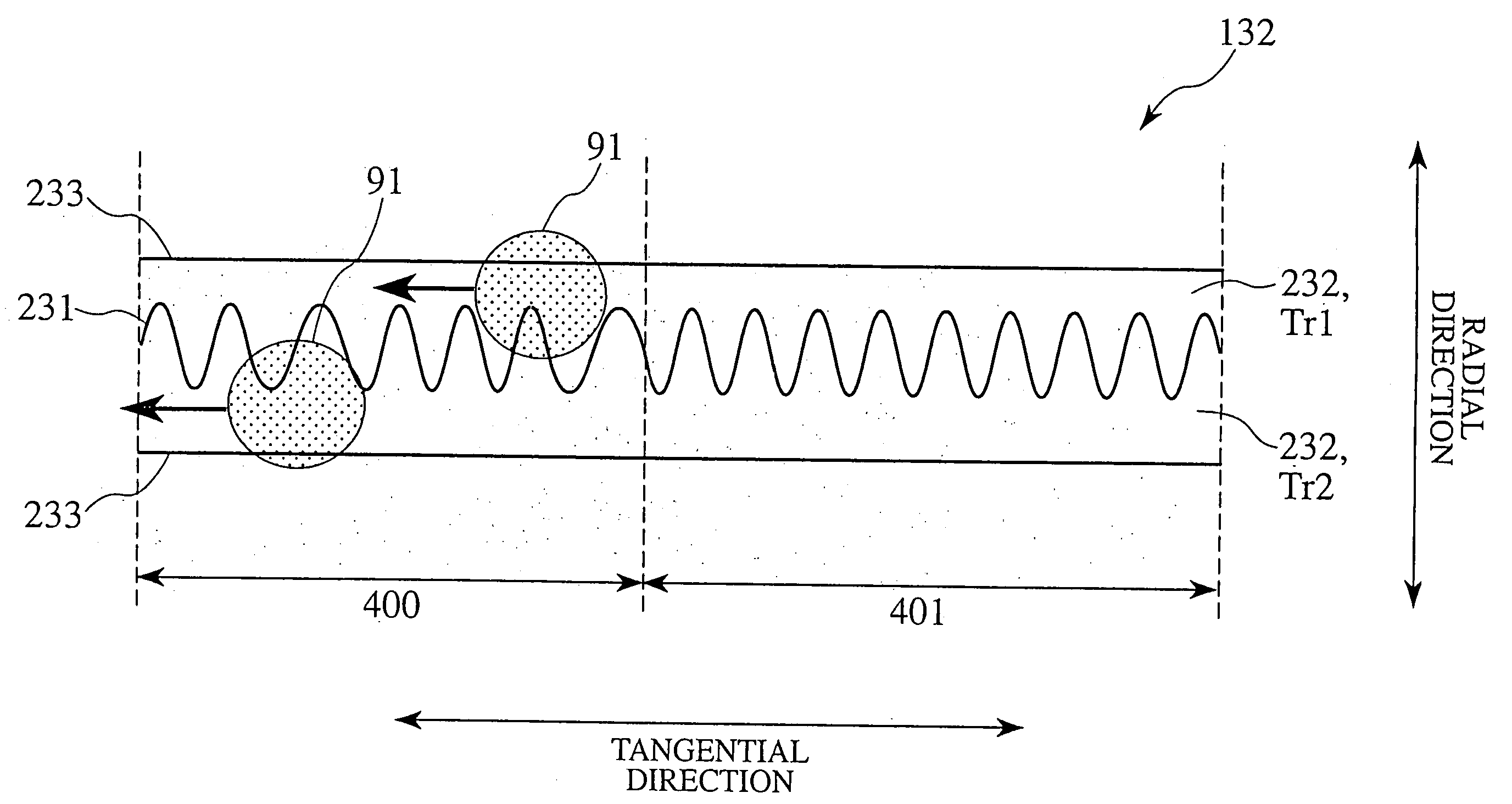
[0247] A disc-like information recording carrier having the structure shown in FIG. 12 was manufactured.

[0248] The pitch P between the track 231 having the wobbling groove region and the track 233 having the linear groove region is 0.32 μm, the width of each groove is 0.16 μm and the width of the inter-groove portion 233 is 0.16 μm.

[0249] The track 231 having the wobbling groove region and the track 233 having the linear groove region are disposed in the land portion L in FIG. 13, while the inter-groove portion 232 is disposed in the groove portion G.

[0250] The track 231 having the wobbling groove region is comprised of address region 400 (5.5 μm long) and clock region 401 and six address regions are disposed each turn.

[0251] The address region 400 and the clock region 401 employ sine wave as their basic waves. The track 233 having the linear groove region employs 360° continuous linear groove.

[0252] In the address region 400, as shown in FIG. 9, by frequency shift modulation i...

example 2

[0260] A disc like information recording carrier 1 having the structure shown in FIG. 12 was manufactured.

[0261] The pitch P between the track 231 having the wobbling groove region and the track 233 having the liner groove region is 0.32 μm, the width of each groove is 0.16 μm and the width of the inter-groove portion 232 is 0.16 μm.

[0262] The track 231 having the wobbling groove region and the track 233 having the linear groove region are disposed in the land L in FIG. 13 and the inter-groove portion 232 is disposed in the groove G.

[0263] The track 231 having the wobbling groove region is comprised of address region 400 (5.5 μm long) and clock region 401 and six address regions are disposed each turn.

[0264] The address region 400 and the clock region 401 employ sine wave as their basic waves. The track 233 having the linear groove region employs 360° continuous linear groove.

[0265] In the address region 400, by frequency shift modulation in which a difference in phase between ...

example 3

[0273] A disc-like information recording carrier having the structure shown in FIG. 12 was manufactured.

[0274] The pitch P between the track 231 having the wobbling groove region and the track 233 having the linear groove region is 0.32 μm, the width of each groove is 0.16 μm and the width of the inter-groove portion 233 is 0.16 μm.

[0275] The track 231 having the wobbling groove region and the track 233 having the linear groove region are disposed in the land portion L in FIG. 13 while the inter-groove portion232 is disposed in the groove portion G.

[0276] The track 231 having the wobbling groove region is comprised of address region 400 (30 μm long) and clock region 401 and three address regions are disposed each turn.

[0277] The address region 400 and the clock region 401 employ sine wave as their basic waves.

[0278] The track 233 having the linear groove region employs 360° continuous linear groove.

[0279] In the address region 400, by frequency shift modulation in which a diff...


PUM

PropertyMeasurementUnit
lengthaaaaaaaaaa
lengthaaaaaaaaaa
total thicknessaaaaaaaaaa

Abstract

An information recording carrier in one mode has minute pattern including plural grooves or lands formed in parallel and adjacent each other and comprises a supporting body having the minute pattern, a recording layer formed on the minute pattern, and a light transmission layer formed on the recording layer. The minute pattern is formed under a relation of p<λ / NA, where a pitch of each groove or land is P, a wavelength of a laser beam is λ and a numerical aperture of an objective lens is NA. The plural grooves or lands have at least a wobbling region where data is recorded wobblingly by frequency shift modulation. A phase relation between the high and the low frequency portion composing the frequency shift modulation is ±(π / 2.5) and the high and the low frequency portion are continuous in phase at a border between the high and the low frequency portion.

Description

BACKGROUND OF THE INVENTION [0001] 1. Field of the Invention [0002] The present invention relates to an information recording carrier for use in system for recording and / or reproducing information by optical means. [0003] 2. Description of the Related Art [0004] Conventionally, a system for reading out information by moving the information recording carrier relatively has been available and optical means, magnetic means and electrostatic capacity means are used for reproducing information therefrom. Of them, the system for recording and / or reproducing information by the optical means has prevailed widely in daily life (“recording / reproducing” mentioned here means three statuses, namely, only recording, only reproduction or recording and reproduction). [0005] For example, as a recording / reproducing type information recording carrier using beam having wavelength λ=650 nm, DVD-RAM, DVD-RW (“DVD” means digital versatile disc) and the like are available. [0006] Although the recording / rep...

Claims


Application Information

Patent Timeline
Patent Type & Authority Applications(United States)
IPC IPC(8): G11B7/24G11B7/005G11B7/007G11B7/24079G11B7/24082G11B7/24085G11B20/14G11B27/19G11B27/24
CPCG11B7/007G11B7/24012G11B7/24038G11B7/24079G11B2220/2575G11B27/24G11B2220/216G11B2220/237G11B2220/2562G11B7/24082
Inventor KONDO, TETSUYA
Owner JVC KENWOOD CORP
Why Eureka
Try Eureka