Information recording carrier and information reproducing apparatus for the same
a technology of information recording and information reproducing apparatus, which is applied in the direction of optical recording/reproducing/erasing methods, rewritable discs, instruments, etc., can solve the problems of user recording rate, mark and pit error rate rise, and the capacity of the entire information recording carrier whose area is limited
- Summary
- Abstract
- Description
- Claims
- Application Information
AI Technical Summary
Benefits of technology
Problems solved by technology
Method used
Image
Examples
example 1
[0242] A disc-like information recording carrier having the structure shown in FIG. 11 was manufactured.
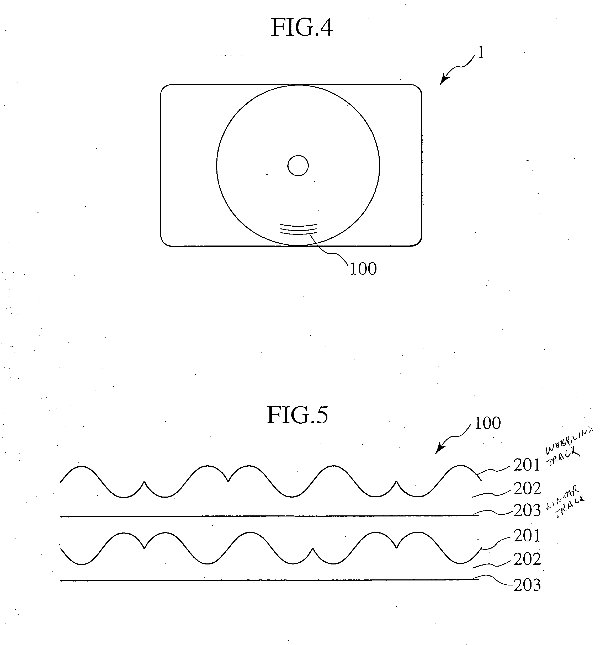
[0243] The pitch P between the track 231 having the wobbling groove region and the track 233 having the linear groove region is 0.32 μm, the width of each groove is 0.16 μm and the width of the inter-groove portion 233 is 0.16 μm.
[0244] The track 231 having the wobbling groove region and the track 233 having the linear groove region are disposed in the land portion L in FIG. 12, while the inter-groove portion 232 is disposed in the groove portion G.
[0245] The track 231 having the wobbling groove region is comprised of address region 400 (5.5 μm long) and clock region 401 and six address regions are disposed each turn.
[0246] The address region 400 and the clock region 401 employ sine wave as their basic waves. The track 233 having the linear groove region employs 360° continuous linear groove.
[0247] In the address region 400, as shown in FIG. 8, using the phase shift modulatio...
example 2
[0255] A disc like information recording carrier 1 having the structure shown in FIG. 11 was manufactured.
[0256] The pitch P between the track 231 having the wobbling groove region and the track 233 having the liner groove region is 0.32 μm, the width of each groove is 0.16 μm, and the width of the inter-groove portion 232 is 0.16 μm.
[0257] The track 231 having the wobbling groove region and the track 233 having the linear groove region are disposed in the land L in FIG. 12. and the inter-groove portion 232 is disposed in the groove G.
[0258] The track 231 having the wobbling groove region is comprised of address region 400 (5.5 μm long) and clock region 401 and six address regions are disposed each turn.
[0259] The address region 400 and the clock region 401 employ sine wave as their basic waves. The track 233 having the linear groove region employs 360° continuous linear groove.
[0260] In the address region 400, as shown in FIG. 7, using the phase shift modulation in which the m...
example 3
[0268] A disc-like information recording carrier having the structure shown in FIG. 12 was manufactured.
[0269] The pitch P between the track 231. having the wobbling groove region and the track 233 having the linear groove region is 0.32 μm, the width of each groove is 0.16 μm and the width of the inter-groove portion 233 is 0.16 μm.
[0270] The track 231 having the wobbling groove region and the track 233 having the linear groove region are disposed in the land portion L in FIG. 13 while the inter-groove portion 232 is disposed in the groove portion G.
[0271] The track 231 having the wobbling groove region is comprised of address region 400 (30 μm long) and clock region 401 and three address regions are disposed each turn.
[0272] The address region 400 and the clock region 401 employ sine wave as their basic waves.
[0273] The track 233 having the linear groove region employs 360° continuous linear groove.
[0274] In the address region 400, as shown in FIG. 8, using the phase shift m...
PUM
| Property | Measurement | Unit |
|---|---|---|
| thickness | aaaaa | aaaaa |
| wavelength | aaaaa | aaaaa |
| length | aaaaa | aaaaa |
Abstract
Description
Claims
Application Information
 - R&D
- Intellectual Property
- Life Sciences
- Materials
- Tech Scout
- Unparalleled Data Quality
- Higher Quality Content
- 60% Fewer Hallucinations
Browse by: Latest US Patents, China's latest patents, Technical Efficacy Thesaurus, Application Domain, Technology Topic, Popular Technical Reports.
© 2025 PatSnap. All rights reserved.Legal|Privacy policy|Modern Slavery Act Transparency Statement|Sitemap|About US| Contact US: help@patsnap.com


