Method of burying metal and apparatus of depositing metal in concave portion

a technology of concave portion and burying metal, which is applied in the direction of resistive material coating, chemical vapor deposition coating, metallic material coating process, etc., can solve the problems of increasing production cost, difficulty in burying metal, and failure to conduct cu-burying in the hole, so as to reduce production cost and increase production speed

Inactive Publication Date: 2013-01-08
CANON ANELVA CORP
View PDF19 Cites 0 Cited by
  • Summary
  • Abstract
  • Description
  • Claims
  • Application Information

AI Technical Summary

Benefits of technology

[0013]According to Patent Document 2, the Cl2 gas is dissociated by plasma to generate Cl radicals in order to generate CuCl vapor by etching the copper plate, and in order to deposit Cu in the hole by the reaction with the generated CuCl vapor. As described above, Cu is deposited by the film-forming reaction between the CuCl vapor and the Cl radicals. When, however, the Cl radicals exist at a high density, the etching reaction of the above-mentioned deposited Cu by the Cl radicals becomes predominant compared with the film-forming reaction, which fails in conducting the Cu-burying in the hole. Consequently, according to Patent Document 2 in order to assure the predominance of the film-forming reaction, it is an essential requirement to control the amount of Cl radicals through the control of Cl2 gas supply rate and of electric power density in generating plasma, and to thereby regulate the rate of the Cu film-forming reaction so as to become slightly larger than the rate of the Cu etching reaction.
[0014]Accordingly, in Patent Document 2, since there occur the Cu-film formation and the etching of the formed Cu film in burying Cu in the hole, it takes a time to complete the burying. Furthermore, since a part of once formed film of Cu is etched, the ratio of the film-formed Cu buried in the hole relative to the consumed amount of copper etched by the Cl radicals decreases, which results in increasing the production cost.
[0015]As described above, the requirements of allowing burying of the metal in a concave portion such as the trench and the via as well as shortening the production time, and reducing the cost of manufacturing apparatus also need to be satisfied.
[0016]The present invention has been derived to cope with the above problems, and an object of the present invention is to provide a method of burying metal and an apparatus of depositing metal in a concave portion, by which metal can be formed in the concave portion while shortening the burying time and reducing the production cost, even in the case of small width of a trench and small diameter of a via.
[0020]According to the present invention, in burying metal in a concave portion, a metal halide layer is formed in the concave portion. Since the metal halide layer is formed in the concave portion by capillary condensation, even if the concave portion is in a fine trench or via, the concave portion can be buried with metal. Furthermore, since the metal halide layer formed during the above-mentioned burying step functions as a protective layer against the halogen gas etching, the etching of the metal being formed under the metal halide layer by the halogen gas can be suppressed, which allows efficient burying of metal. As a result, the production speed can be increased and the production cost can be decreased.

Problems solved by technology

However, when the width of trench or the diameter of via becomes smaller, there arises a problem common to conventional sputtering technology and to conventional film-forming method using organic metal complexes of plugging the inlet of opening of the trench or the via at the time of forming metal film, which results in difficulty in burying the metal.
When, however, the Cl radicals exist at a high density, the etching reaction of the above-mentioned deposited Cu by the Cl radicals becomes predominant compared with the film-forming reaction, which fails in conducting the Cu-burying in the hole.
Furthermore, since a part of once formed film of Cu is etched, the ratio of the film-formed Cu buried in the hole relative to the consumed amount of copper etched by the Cl radicals decreases, which results in increasing the production cost.

Method used


Image

  • Method of burying metal and apparatus of depositing metal in concave portion
  • Method of burying metal and apparatus of depositing metal in concave portion
  • Method of burying metal and apparatus of depositing metal in concave portion

Examples


example 1

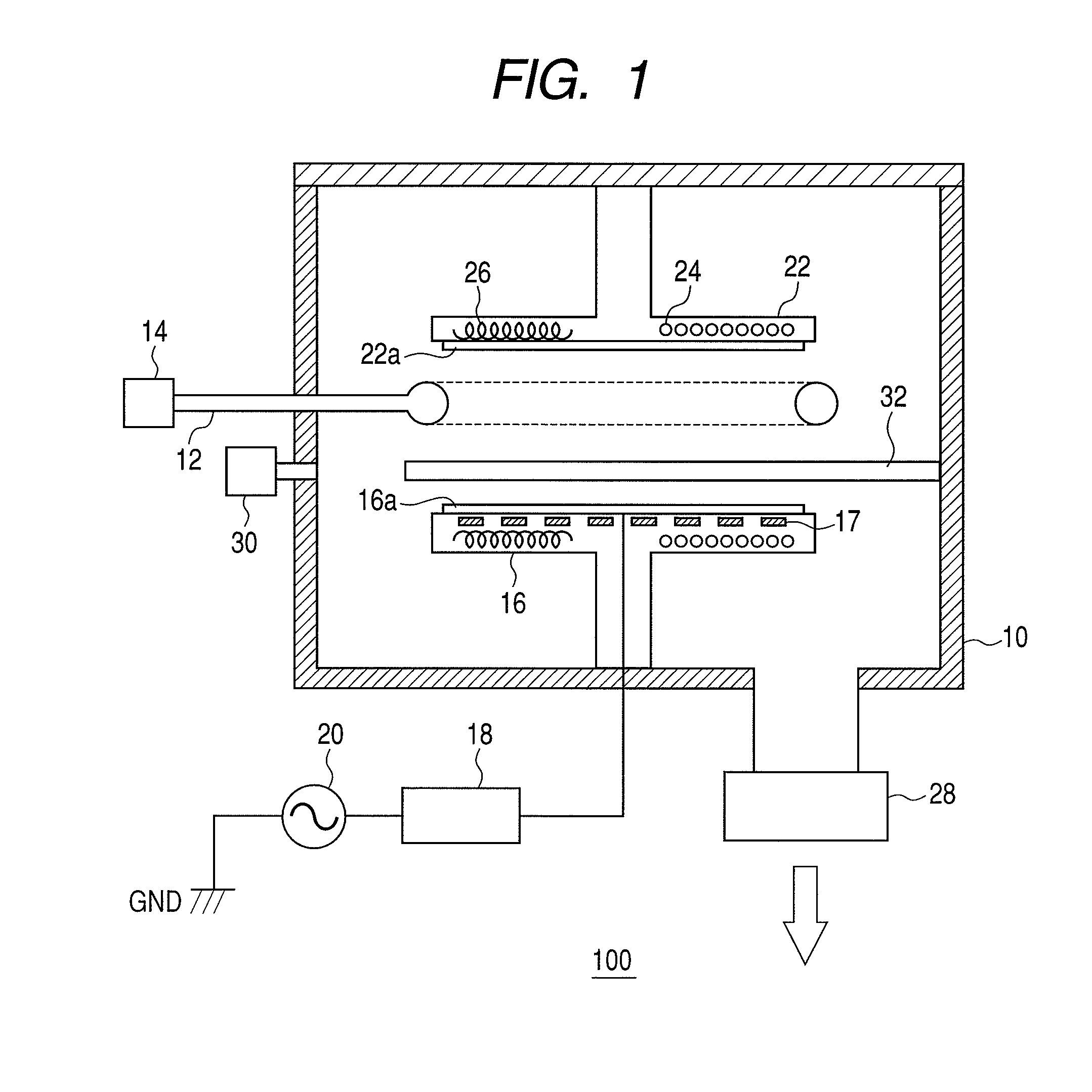
[0077]Example 1 will be described below. Example 1 used the wiring-forming apparatus given in FIG. 1. In this Example, the applied substrate 22a was a silicon substrate which was prepared by forming sequentially a silicon nitride film and a silicon oxide film on the surface of the substrate, and by forming vias having a diameter of 0.16 μm as the silicon oxide film, as illustrated in FIG. 3. The aspect ratio of the via was 2.3 as a via-top basis and was 3.0 as a via-bottom basis. The supplied gas was a chlorine (Cl2) gas diluted by argon (Ar). The concentration of the Cl2 gas was set as 3.4% by volume, and the total pressure was adjusted to 1.3 Pa. Furthermore, the target 16a was a copper plate. That is, the pressure of the gas ambient at the time forming metal vapor and wiring, (the total pressure at the time of forming the metal vapor and wiring (the pressure at the time depositing metal in the concave portion), or the total pressure in the chamber 10), was 1.3 Pa.

[0078]Before con...

example 2

[0086]Instead of the above-mentioned conditions, when the supply gas was prepared by diluting chlorine gas (Cl2) by using argon (Ar) to 3.4% by volume, and the total pressure was adjusted to 1.3 Pa, the copper was formed on the surface of the substrate 22a. Except that the substrate temperature was decreased by several degrees Centigrade, other conditions were the same as those in Example 1.

[0087]In this case, as shown in SEM surface observation in FIG. 7 and in SEM cross-section observation in FIG. 8, entire vias made it possible to be buried with copper. Meanwhile, the vias were arranged in a regular grid pattern inclined in 45 degrees. As shown in SEM surface observation in FIG. 7, the copper was buried inside the vias and was overflowed outside the via on the substrate 22a. The measurement of the formed copper by using XRF gave the atomic ratio of chlorine (Cl) relative to copper (Cu) of 0.48, which showed that the chlorine-containing copper was formed.

[0088]As described above, ...


PUM

PropertyMeasurementUnit
diameteraaaaaaaaaa
temperatureaaaaaaaaaa
pressureaaaaaaaaaa

Abstract

The present invention provides the technology for burying metal even in a fine concave portion such as trench and via. According to an embodiment of the present invention, a vapor of the metal as the objective material, a gas containing halogen for etching the metal, and a metal halide vapor made up of the metal element and the halogen element are supplied to the substrate, which thus forms a metal halide layer in the concave portion, and thereby deposits the metal under the metal halide layer. The procedure can achieve the above object.

Description

CROSS-REFERENCES TO RELATED APPLICATIONS[0001]This application is a continuation application of International Application No. PCT / JP2009 / 052543, filed on Feb. 16, 2009, the entire contents of which are incorporated by reference herein.[0002]This application also claims the benefit of priority from Japanese Patent Application No. 2008-034985 filed Feb. 15, 2008, the entire contents of which are incorporated herein by reference.TECHNICAL FIELD[0003]The present invention relates to a method of burying metal and an apparatus of depositing metal in a concave portion.BACKGROUND ART[0004]Design of semiconductor devices moves toward further high-speed and low-loss characteristics, which raises requirements of increased density and fineness of wiring in the circuit therein. The minimum wiring width currently required is several tens of nanometers. To satisfy such requirements, the aluminum alloy wiring has been substituted by copper wiring which has lower resistivity and more superior durabi...

Claims


Application Information

Patent Timeline
Patent Type & Authority Patents(United States)
IPC IPC(8): C23C16/00C23C14/34
CPCC23C14/0057C23C14/046C23C14/14H01L21/2855H01L21/28562H01L21/76879
Inventor NODA, SUGURUTAKASHIMA, SATOSHI
Owner CANON ANELVA CORP
Why Eureka
Try Eureka