Methods and apparatus for targeted sound detection and characterization

a targeted sound detection and characterization technology, applied in signal processing, transducer details, electrical transducers, etc., can solve the problems of inability to meet the needs of consumer electronics applications, directional microphones are unsuitable for applications in consumer electronics, and the technique is computationally intensive and not robus

Active Publication Date: 2006-10-19
SONY COMPUTER ENTERTAINMENT INC
View PDF98 Cites 222 Cited by
  • Summary
  • Abstract
  • Description
  • Claims
  • Application Information

AI Technical Summary

Benefits of technology

[0007] Embodiments of the invention are directed to methods and apparatus for targeted sound detection. In embodiments of the invention may be implemented with a microphone array having two or more microphones M0 . . . . MM. Each microphone is coupled to a plurality of filters. The filters are configured to filter input signals corresponding to sounds detected by the microphones thereby generating a filtered output. One or more sets of filter parameters for the plurality of filters are pre-calibrated to determine one or more corresponding pre-calibrated listening zones. Each set of filter parameters is selected to detect portions of the input signals corresponding to sounds originating within a given listening zone and filter out sounds originating outside the given listening zone. A particular pre-calibrated listening zone is selected at a runtime by applying to the plurality of filters a set of filter coefficients corresponding to the particular pre-calibrated listening zone. As a result, the microphone array may detect sounds originating within the particular listening sector and filter out sounds originating outside the particular listening zone. Sounds are detected with the microphone array. A particular listening zone containing a source of the sound is identified. The sound or the source of the sound is characterized and the sound is emphasized or filtered out depending on how the sound is characterized.

Problems solved by technology

Although such directional microphones are available they tend to be either bulky or expensive or both.
Consequently such directional microphones are unsuitable for applications in consumer electronics.
Although effective, this technique is computationally intensive and is not robust.
Such drawbacks make such techniques unsuitable for use in hand-held devices and consumer electronic applications, such as video game controllers.

Method used


Image

  • Methods and apparatus for targeted sound detection and characterization
  • Methods and apparatus for targeted sound detection and characterization
  • Methods and apparatus for targeted sound detection and characterization

Examples


Embodiment Construction

[0022] Although the following detailed description contains many specific details for the purposes of illustration, anyone of ordinary skill in the art will appreciate that many variations and alterations to the following details are within the scope of the invention. Accordingly, the exemplary embodiments of the invention described below are set forth without any loss of generality to, and without imposing limitations upon, the claimed invention.

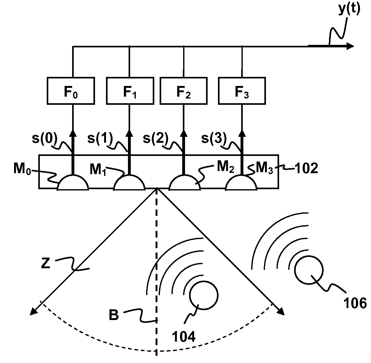
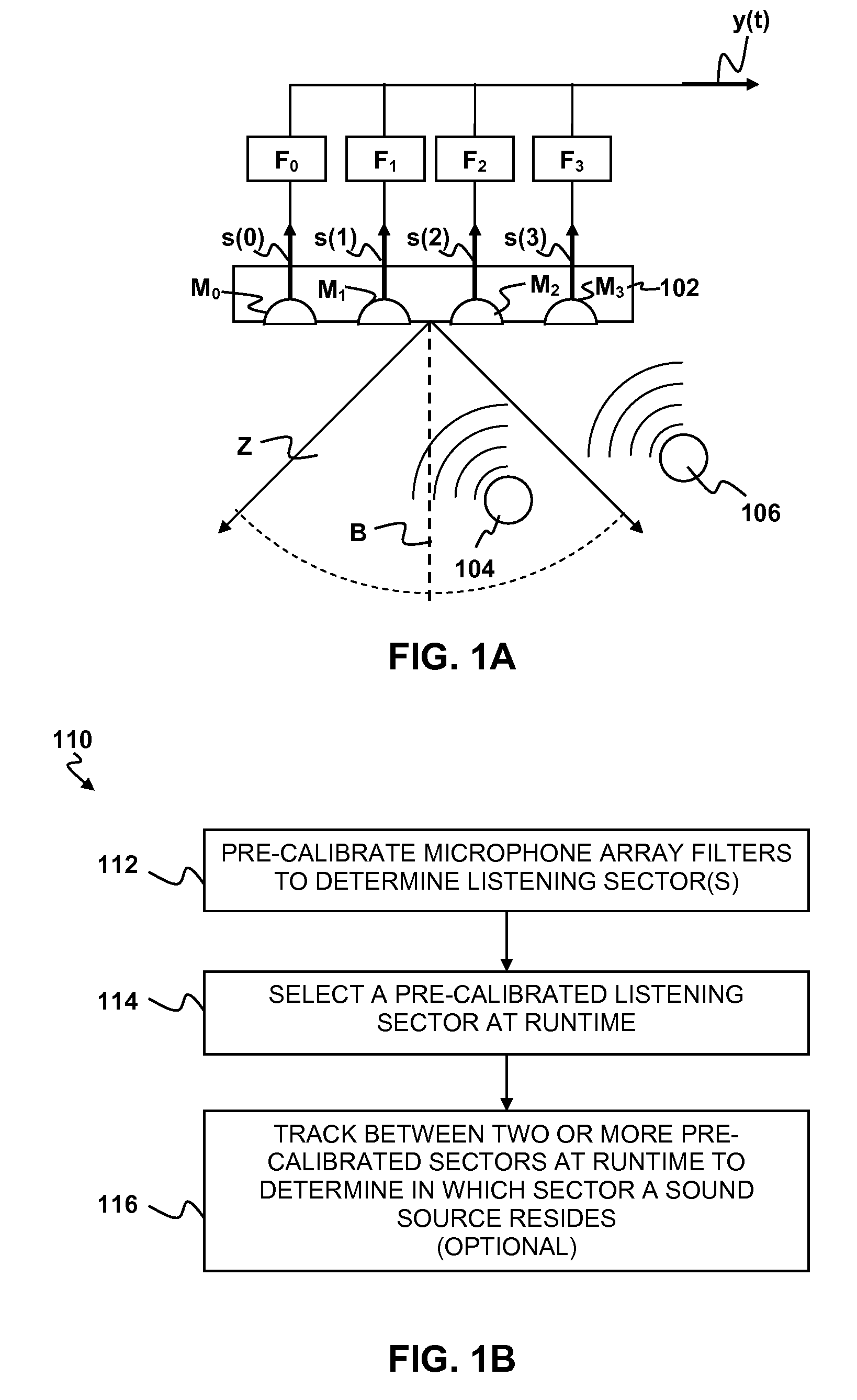
[0023] As depicted in FIG. 1A, a microphone array 102 may include four microphones M0, M1, M2, and M3 that are coupled to corresponding signal filters F0, F1, F2 and F3. Each of the filters may implement some combination of finite impulse response (FIR) filtering and time delay of arrival (TDA) filtering. In general, the microphones M0, M1, M2, and M3 may be omni-directional microphones, i.e., microphones that can detect sound from essentially any direction. Omni-directional microphones are generally simpler in construction and less expens...


PUM


Abstract

Targeted sound detection methods and apparatus are disclosed. A microphone array has two or more microphones M0 . . . MM. Each microphone is coupled to a plurality of filters. The filters are configured to filter input signals corresponding to sounds detected by the microphones thereby generating a filtered output. One or more sets of filter parameters for the plurality of filters are pre-calibrated to determine one or more corresponding pre-calibrated listening zones. Each set of filter parameters is selected to detect portions of the input signals corresponding to sounds originating within a given listening zone and filter out sounds originating outside the given listening zone. A particular pre-calibrated listening zone is selected at a runtime by applying to the plurality of filters a set of filter coefficients corresponding to the particular pre-calibrated listening zone. As a result, the microphone array may detect sounds originating within the particular listening sector and filter out sounds originating outside the particular listening zone. Sounds are detected with the microphone array. A particular listening zone containing a source of the sound is identified. The sound or the source of the sound is characterized and the sound is emphasized or filtered out depending on how the sound is characterized.

Description

CROSS-REFERENCE TO RELATED APPLICATION [0001] This Application claims the benefit of priority of U.S. Provisional Patent Application No. 60 / 678,413, filed May 5, 2005, the entire disclosures of which are incorporated herein by reference. This Application claims the benefit of priority of U.S. Provisional Patent Application No. 60 / 718,145, filed Sep. 15, 2005, the entire disclosures of which are incorporated herein by reference. This application is a continuation-in-part of and claims the benefit of priority of commonly-assigned U.S. patent application Ser. No. 10 / 650,409, filed Aug. 27, 2003 and published on Mar. 3, 2005 as U.S. Patent Application Publication No. 2005 / 0047611, the entire disclosures of which are incorporated herein by reference. This application is a continuation-in-part of and claims the benefit of priority of commonly-assigned, U.S. patent application Ser. No. 10 / 759,782 to Richard L. Marks, filed Jan. 16, 2004 and entitled: METHOD AND APPARATUS FOR LIGHT INPUT DE...

Claims


Application Information

Patent Timeline
Patent Type & Authority Applications(United States)
IPC IPC(8): H04R3/00
CPCH04R1/406H04R3/005H04R2430/23H04R2201/403H04R29/005
Inventor MAO, XIADONGMARKS, RICHARD L.ZALEWSKI, GARY M.
Owner SONY COMPUTER ENTERTAINMENT INC
Why Eureka
Try Eureka