Collapsible vacuum device

Inactive Publication Date: 2006-10-19
NANMA MFG
View PDF11 Cites 14 Cited by
  • Summary
  • Abstract
  • Description
  • Claims
  • Application Information

AI Technical Summary

Benefits of technology

[0005] A primary object of the present invention is to provide a vacuum device that maintains a sufficient degree of vacuum insid

Problems solved by technology

However, a sleeve member of the prior art adapted to engage the penis in such vacuum devices is designed to only maintain a sufficient degree of vacuum inside the dev

Method used


Image

  • Collapsible vacuum device
  • Collapsible vacuum device
  • Collapsible vacuum device

Examples


Embodiment Construction

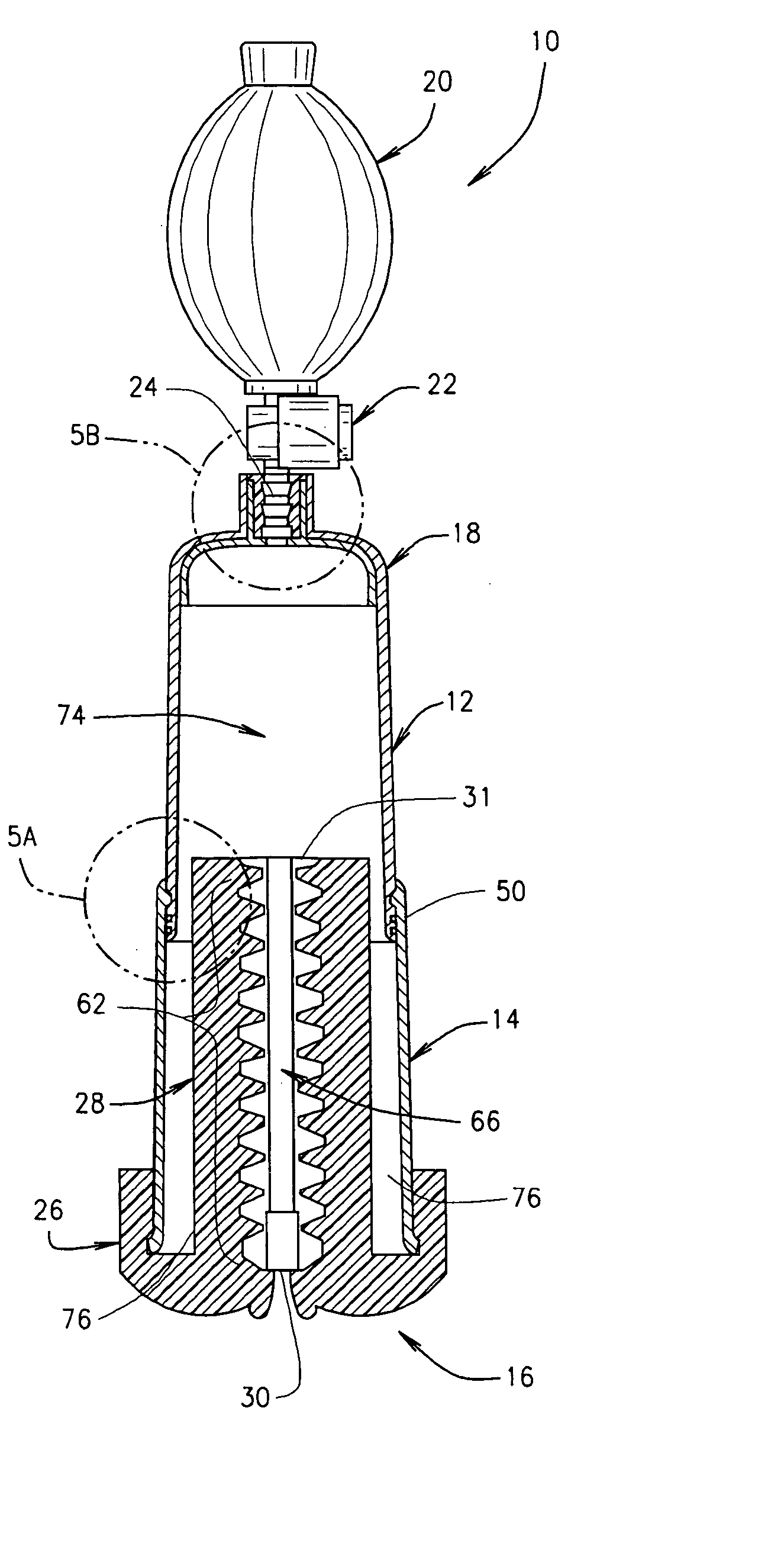
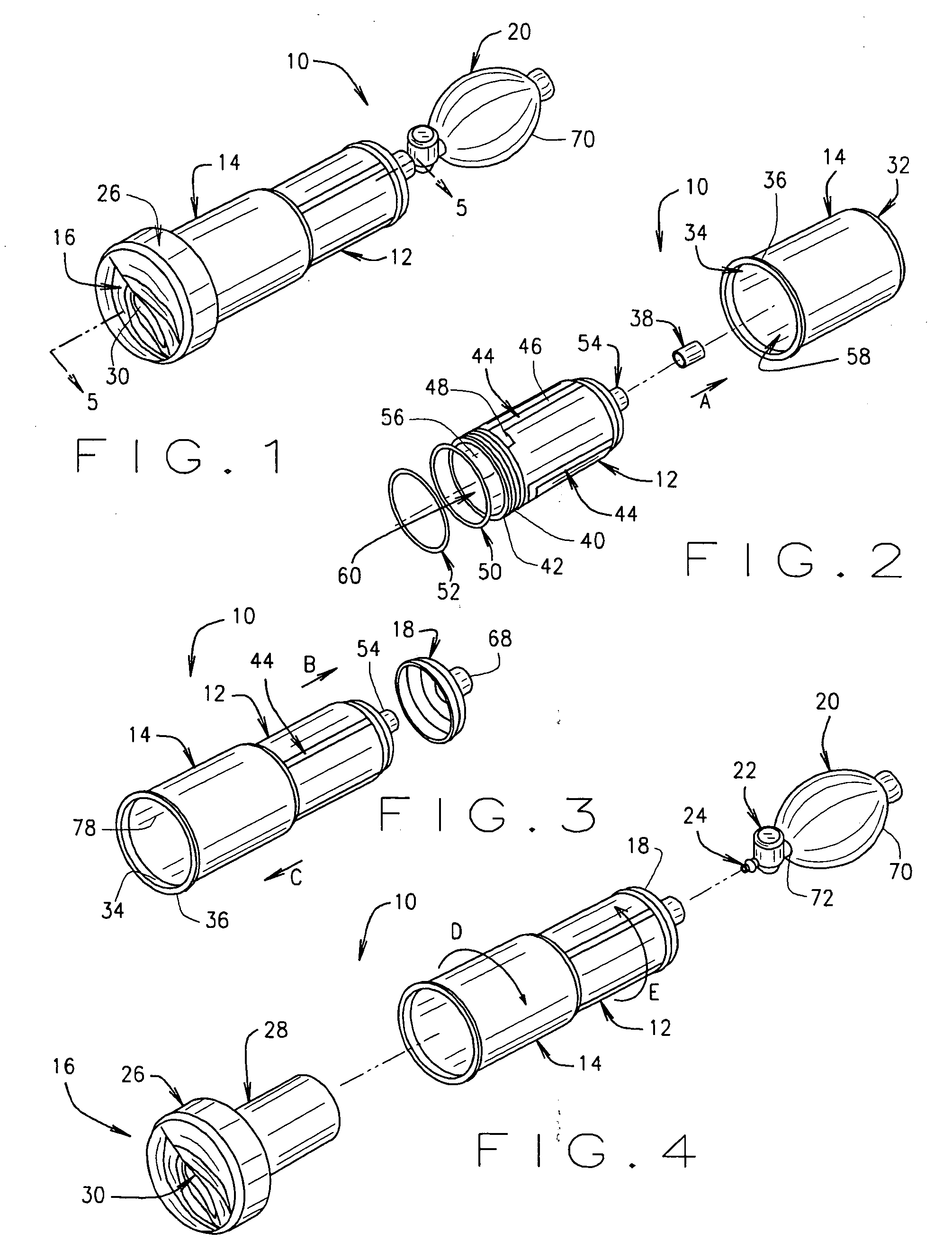
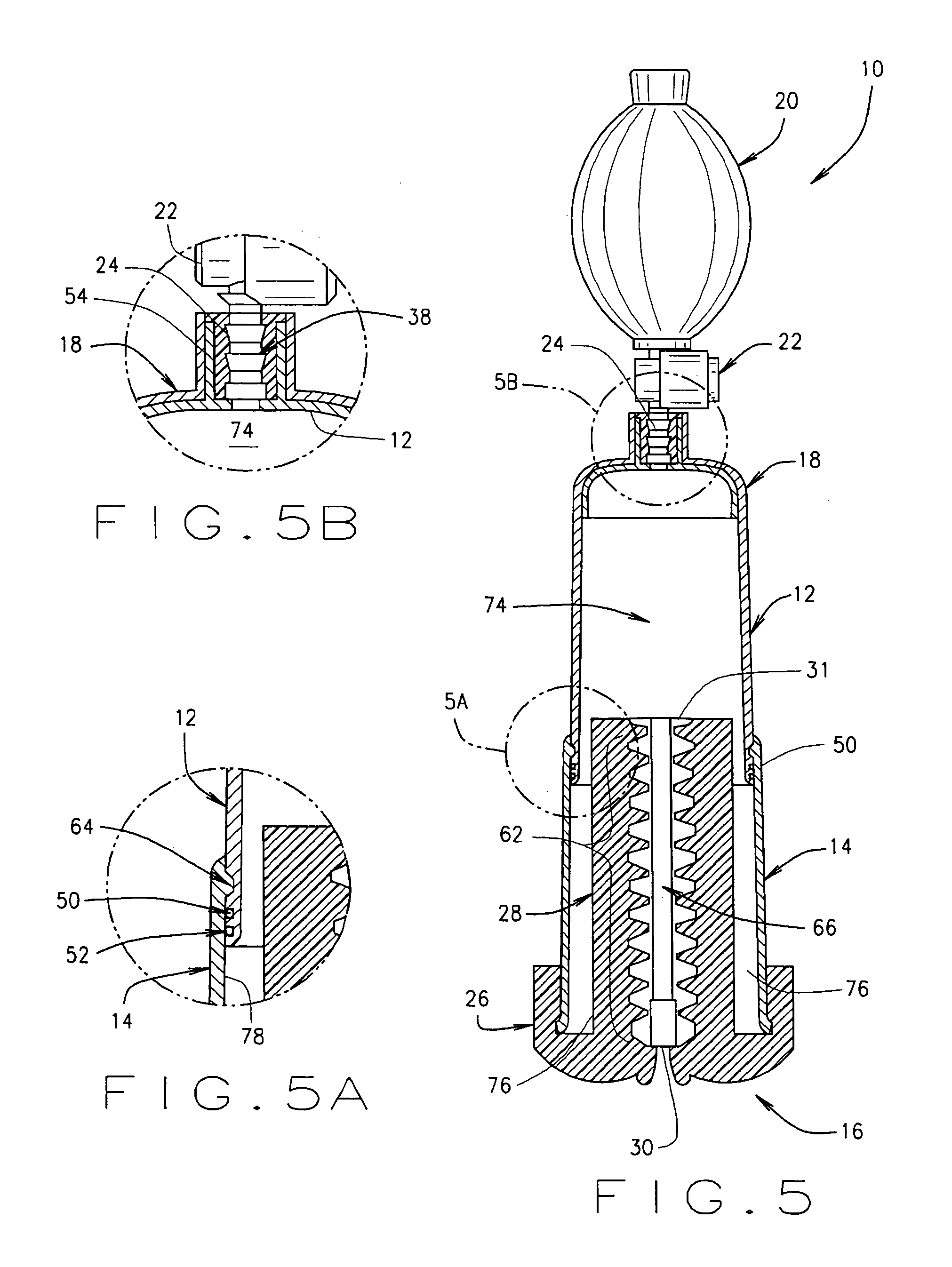
[0026] Referring to the drawings, a vacuum device according to the present invention is illustrated and generally indicated as 10 in FIGS. 1-5. The vacuum device 10 comprises an inner tubular member 12 slidably engageable within an outer tubular member 14 adapted to be assembled in an operational configuration (FIG. 1) or quickly disassembled in a storage configuration (FIG. 5).

[0027] Referring to FIG. 2, the outer tubular member 14 defines a large bore 58 in communication with a proximal opening 32 and an opposing distal opening 34, while the inner tubular member 12 defines a small bore 60 in communication with a circular protrusion 54 at one end and a large opening 56 at another end. A sleeve 38 is adapted to be engaged within the circular protrusion 54. The vacuum device 10 further comprises a sleeve member 16 adapted to be disposed inside the large bore 58 through the large opening 56. The sleeve member 16 is adapted for maintaining sufficient vacuum inside the vacuum device 10...


PUM


Abstract

A vacuum device for facilitating the attainment of a penile erection is disclosed. The vacuum device comprises an inner tubular member slidably engaged with an outer tubular member with a sleeve member disposed inside the inner tubular member. The sleeve member defines a conduit having a plurality of nub-like protrusions adapted to maintain a sufficient degree of vacuum inside the device while simultaneously providing a massaging action.

Description

FIELD OF THE INVENTION [0001] The present invention relates to an apparatus for assisting the user to attain a penile erection, and more particularly to a vacuum penile erection device. BACKGROUND OF THE INVENTION [0002] Vacuum penile erection devices for the treatment of impotence that assist the user in attaining a penile erection are well known in the art. Typically, such vacuum devices may comprise a hollow tubular member having an opening in communication with a cavity adapted to receive the penis. In addition, the tubular member may be in operative communication with a manual vacuum generating means, such as a flexible bulb or piston, for generating a vacuum inside the tubular member when the user repeatedly actuates the bulb or piston. A sleeve member may be disposed inside the tubular member that is adapted to engage the penis in order to maintain a sufficient level of vacuum between the penis and the tubular member during operation of the vacuum device. In addition, the sle...

Claims


Application Information

Patent Timeline
IPC IPC(8): A61F5/00A61H7/00
CPCA61F5/41A61H2201/165A61H9/005A61F2005/412
Inventor NAN, SIMON SIU MAN
Owner NANMA MFG
Why Eureka
Try Eureka