
Method and apparatus for positioning a cutting tool for orthopedic surgery using a localization system

a surgical navigation system and cutting tool technology, applied in the field of surgical navigation systems, can solve problems such as difficulty in accurately positioning cutting tools for surgeons

Inactive Publication Date: 2006-10-19
AESCULAP AG
View PDF29 Cites 92 Cited by
  • Summary
  • Abstract
  • Description
  • Claims
  • Application Information

AI Technical Summary

Benefits of technology

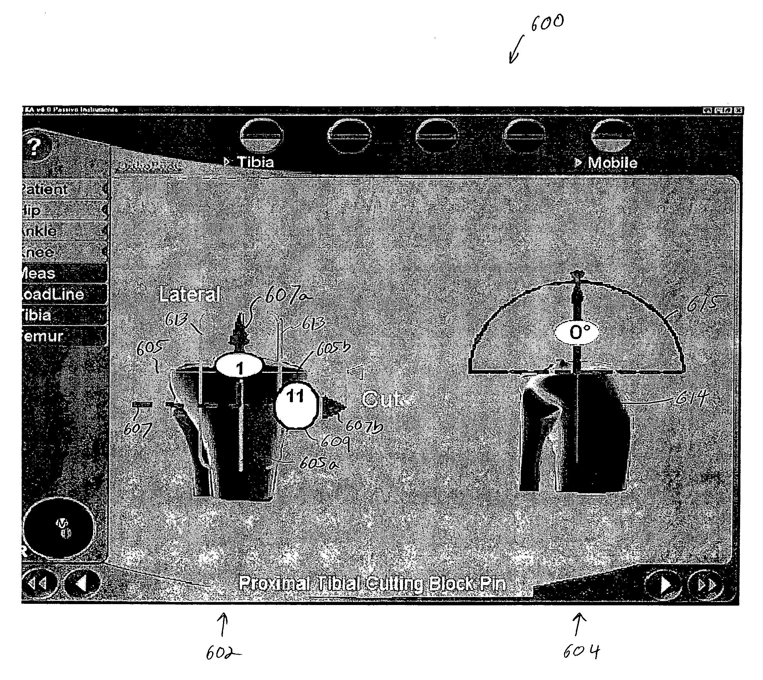
[0016] The present invention provides methods and apparatus that overcome the aforementioned problems by permitting one to position a cutting jig or other component using a localization device to navigate different degrees of freedom of the component in discrete, sequential steps. In one embodiment for mounting a cutting jig, for instance, a first mounting pin for the cutting jig that sets one or more, but fewer than all, degrees of freedom of the cutting jig is navigated into position using the localization device. For instance, the first mounting pin (navigated) might set the height and the slope of the cut

Problems solved by technology

Some surgeons find it difficult to position a jig accurately using surgical navigation systems because they must precisely position the cutting jig on the bone in multiple degrees of freedom while trying to looking at both the computer monitor and the patient's knee, and then mount the jig to the bone with two or more pins using a power tool while not moving the jig.

Method used


Image

  • Method and apparatus for positioning a cutting tool for orthopedic surgery using a localization system
  • Method and apparatus for positioning a cutting tool for orthopedic surgery using a localization system
  • Method and apparatus for positioning a cutting tool for orthopedic surgery using a localization system

Examples


Embodiment Construction

[0029] A description of a suitable localization device for use in connection with the present invention is found in U.S. Pat. No. 6,385,475 to Cinquin et al., incorporated herein by reference.

[0030] In order to assist the surgeon in this task, a surgical navigation system, for example, may display a screen such as the screen 312 shown in FIG. 3 which provides both a frontal view 313 and a lateral (also called sagittal) view 314 of the tibia and the cutting jig. In both views, a green cross-hair 316 (green being represented by the lighter lines) represents the mechanical axis of the tibia, with the vertical line 316a representing the mechanical axis of the tibia and the horizontal line 316b representing the plane perpendicular to that mechanical axis. The horizontal line 316b also represents the height of the tibial plateau in the frontal view 313. In the lateral view 314, the position of the line 316b is irrelevant. A red semicircle 330 (red being represented by the heavier lines i...


PUM


Abstract

The present invention provides methods and apparatus that permit one to position a cutting jig or other component using a localization device to navigate different degrees of freedom of the component in discrete, sequential steps. For instance, a first mounting pin for a cutting jig that sets one or more, but fewer than all, degrees of freedom of the cutting jig is navigated into position using the localization device. For instance, the first mounting pin might set the height and the slope of the cutting plane of the jig. Next, a marker is mounted on the cutting jig and the cutting jig is slid onto the mounted pin. Then the cutting block is navigated in another degree of freedom, for instance, to set the varus-valgus angle of the cutting plane by rotating the jig about the axis of the pin. A second mounting pin for the jig is affixed to the bone based on that navigation.

Description

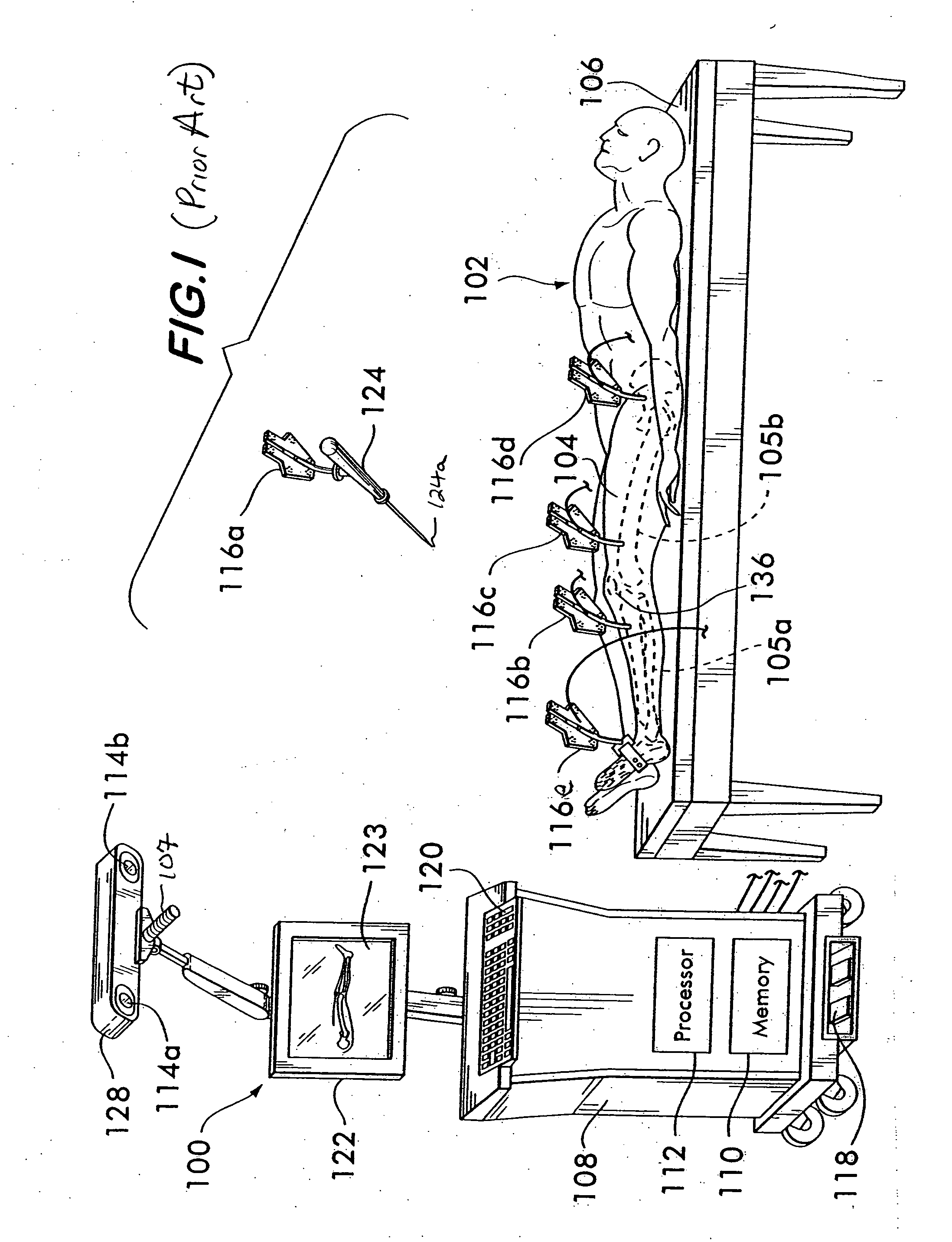
CROSS REFERENCE TO RELATED APPLICATION [0001] This application claims priority under 35 U.S.C. §119(e) to U.S. provisional patent application No. 60 / 668,048 filed Apr. 4, 2005, which is fully incorporated herein by reference.FIELD OF THE INVENTION [0002] The present invention relates to surgical navigation systems, sometimes called localization devices. More particularly, the present invention relates to methods and apparatus for positioning a cutting tool for orthopedic surgery using a surgical navigation system. BACKGROUND OF THE INVENTION [0003] In an exemplary surgical navigation system 100 such as illustrated in FIG. 1, at least two sensors 114a, 114b (e.g., infrared cameras) mounted in a housing 128 are used to detect a plurality of markers 116a, 116b, 116c, 116d, 116e that can be mounted on the patient's bones 105a, 105b and / or on surgical tools 124. More particularly, the cameras 114a, 114b are coupled to a computer 112 that analyzes the images obtained by the cameras and de...

Claims


Application Information

Patent Timeline
IPC IPC(8): A61B5/05
CPCA61B17/157A61B17/3421A61B2019/5255A61B19/56A61B19/5244A61B34/20A61B34/25A61B2034/2055
Inventor GABRIEL, CHRISTIANLEITNER, FRANCOISSCHILL, RICHARD
Owner AESCULAP AG
Learn More