Virtual forward lean snowboard binding

a technology of snowboard bindings and forward leaning, which is applied in snowboard bindings, skis, skiing, etc., can solve the problems of not optimally positioning the highback with respect to the rider's ankle, and achieve the effect of facilitating the movement of the board

Inactive Publication Date: 2006-10-26
K 2 CORP
View PDF64 Cites 33 Cited by
  • Summary
  • Abstract
  • Description
  • Claims
  • Application Information

AI Technical Summary

Benefits of technology

[0007] The present invention is directed to a binding for gliding boards such as snowboards, and includes a base plate that attaches to the board, a heel loop that attaches to a rearward portion of the base plate, and a highback that is pivotably attached to the heel loop. The highback provides support for the rider and facilitates moving the board generally about its longitudinal axis. By pivoting the highback, it can be set to any of a range of maximum forward lean settings to accommodate the rider's preferences. In the present invention, the highback pivots about a virtual axis that is approximately located to correspond with the natural axis of the rider's ankle for rotation in dorsiflexion / plantar flexion.

Problems solved by technology

However, because the dorsiflexion ankle joint is located higher than the other joints in the ankle, snowboard binding designers have had to compromise in order not to interfere with the other ankle joints and the highback portion of prior art bindings is generally constructed to pivot about an axis that is well below the dorsiflexion ankle joint.
The result is that the highback is not optimally positioned with respect to the rider's ankle over the design range of settings for the maximum forward lean position.

Method used


Image

  • Virtual forward lean snowboard binding
  • Virtual forward lean snowboard binding
  • Virtual forward lean snowboard binding

Examples


Embodiment Construction

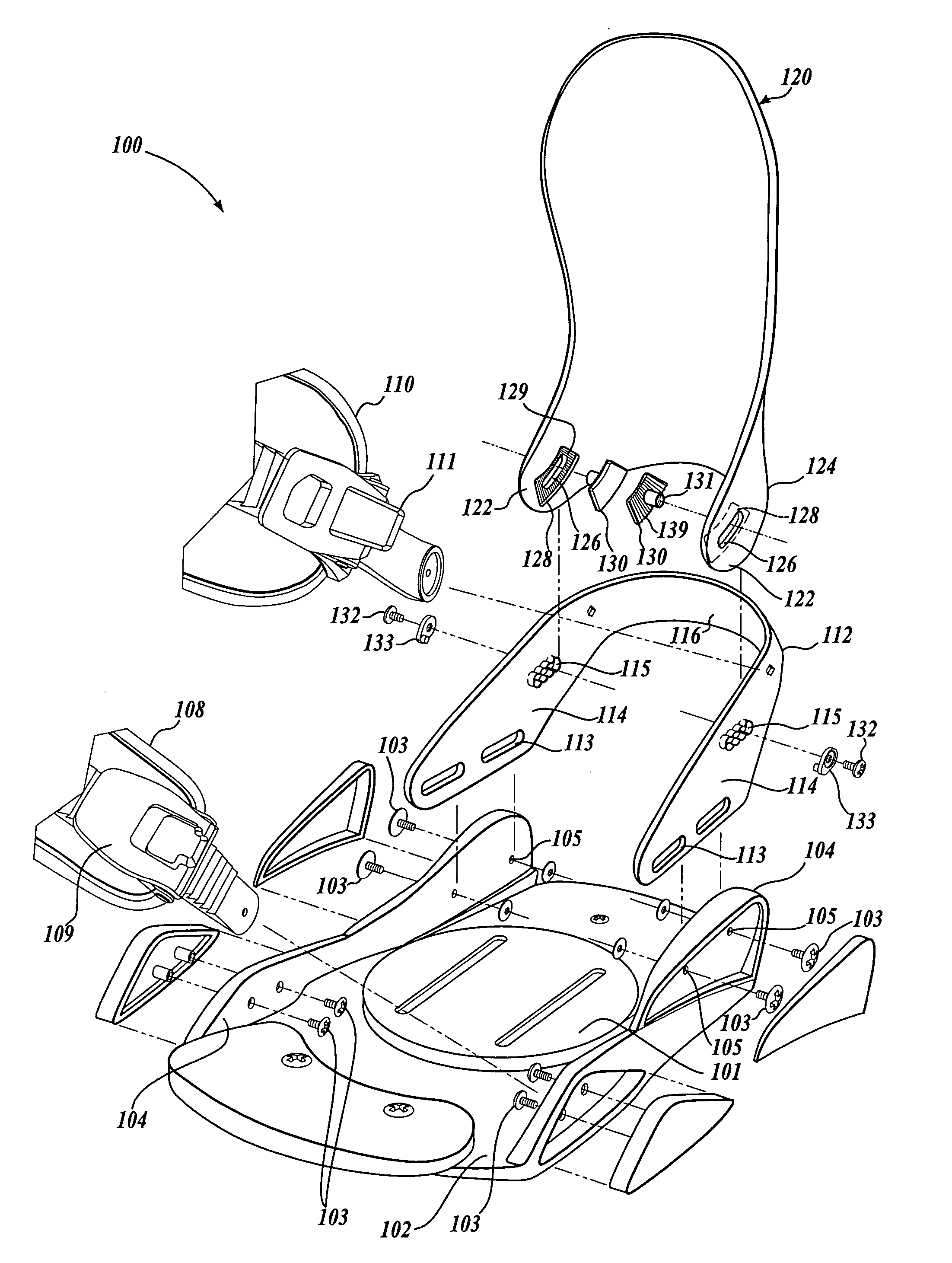
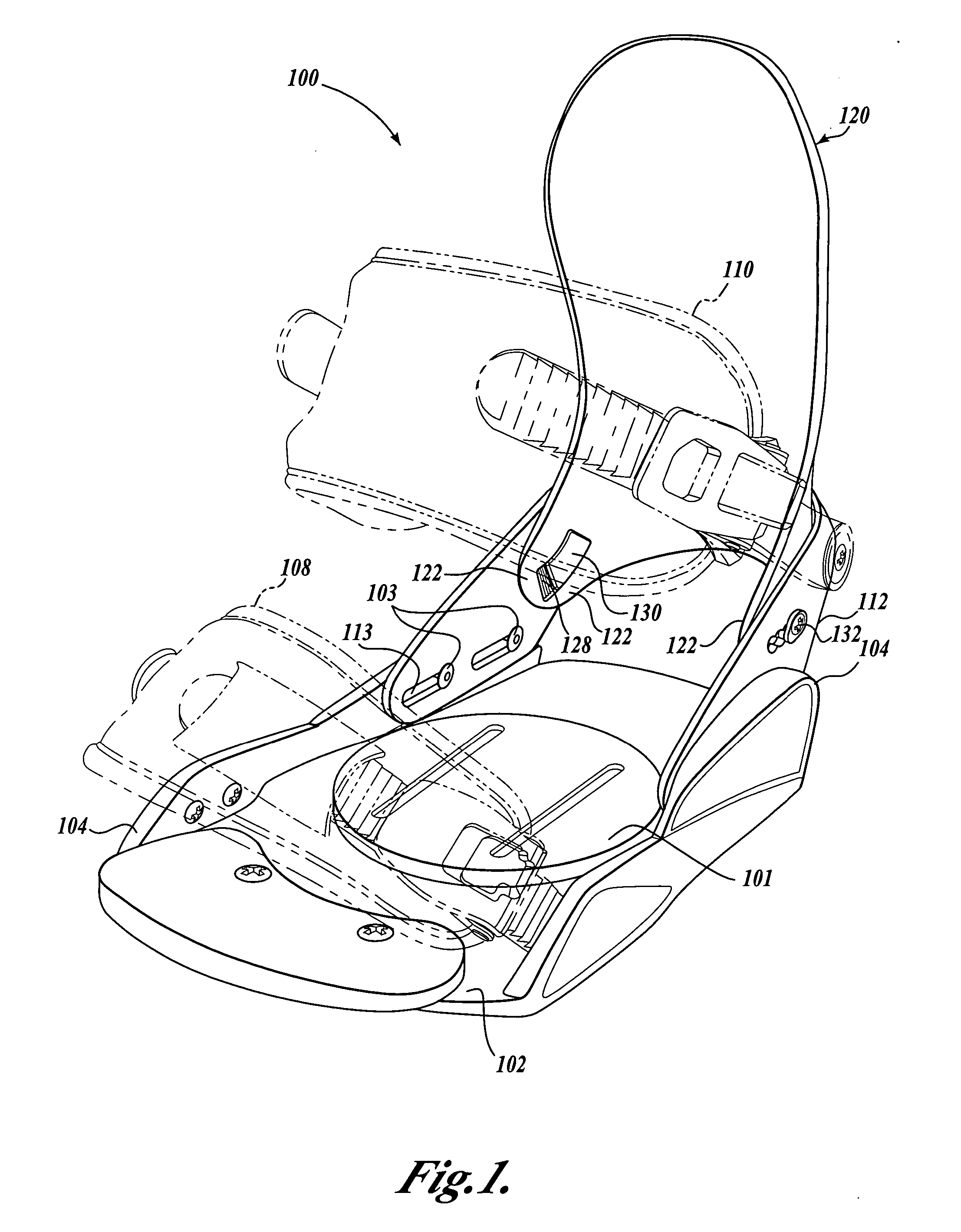
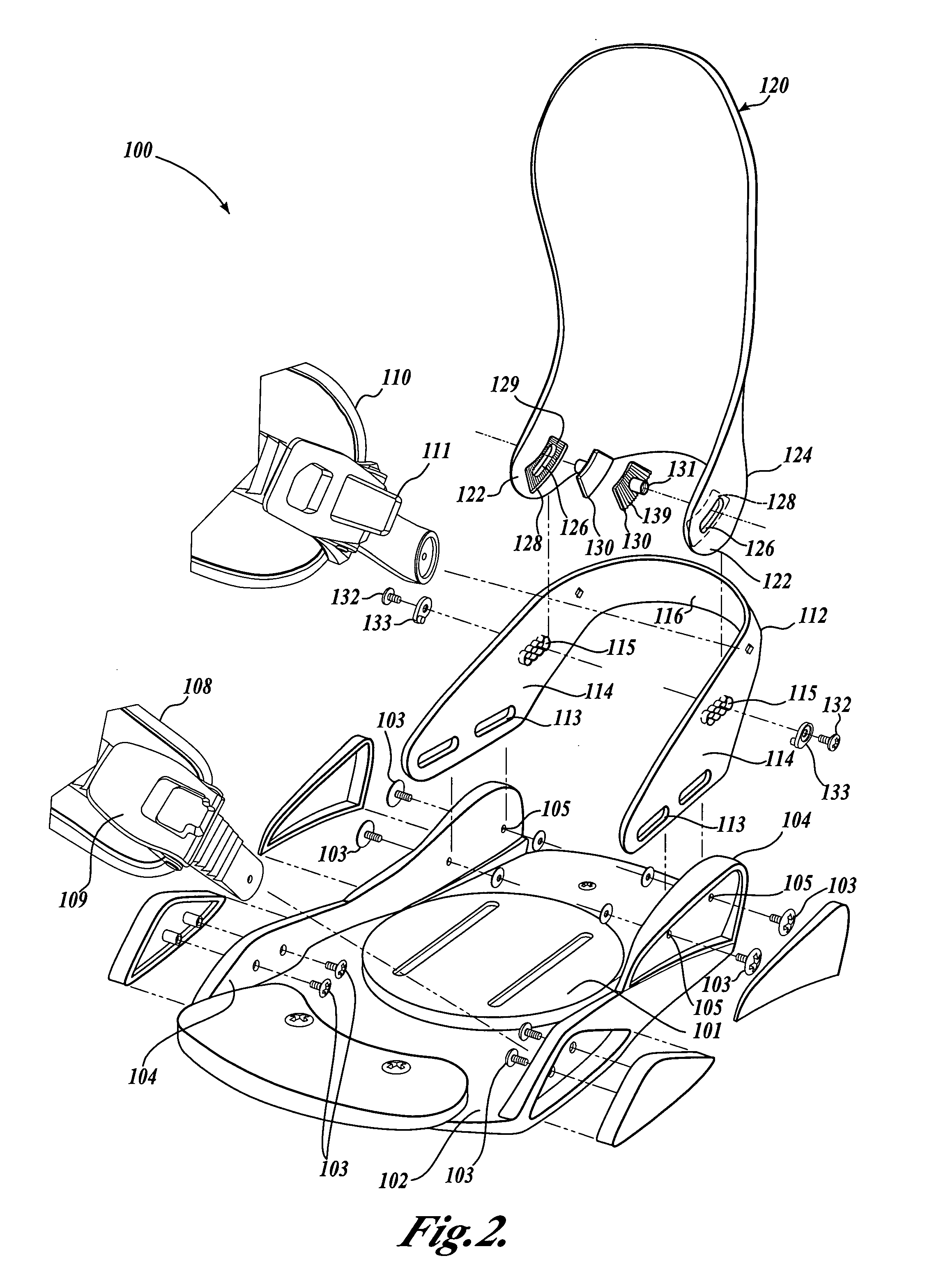
[0018] Refer now to the figures, wherein like numbers indicate like parts. FIG. 1 is a perspective view of a snowboard binding 100 illustrating a currently preferred embodiment to the present invention and FIG. 2 shows an exploded view of the snowboard binding 100. It should be appreciated that the binding 100 includes certain general aspects in common with the commonly-owned U.S. Pat. No.5,727,797, to Bowles, which is hereby incorporated by reference in its entirety.

[0019] The binding 100 includes a base plate 102 that is adapted to be selectively attached to a snowboard (not shown) by conventional attachment mechanisms as are well known in the art—for example, with fastening hardware extending through apertures in an adjustment disk 101. The base plate 102 provides a platform for receiving the snowboard boot (not shown) of a rider and includes a pair of oppositely disposed sidewalls 104. A generally U-shaped heel loop 112 is attached to the base plate 102 with attachment hardware...


PUM


Abstract

A snowboard binding (100) is disclosed having a base plate (102) with a pair of oppositely disposed sidewalls (104), a heel loop (112) attached to the base plate, and a highback (120). The highback is attached to the heel loop such that the highback is pivotable about a virtual axis that is disposed away from the base plate and away from the highback. The virtual axis is preferably coaxial with the ankle's rotational axis for dorsiflexion. In an embodiment of the invention the highback includes arcuate slots (126) through which a bolt (132) and curved nut plate (130) attach the highback to the heel loop. The arcuate slot is preferably a circular arc centered on the desired virtual axis. In an embodiment of the invention, the heel loop intermediate portion (116) is curved about a transverse axis, and the heel portion (124) of the highback is similarly curved to generally nest with the heel loop.

Description

FIELD OF THE INVENTION [0001] The present invention is directed to bindings for gliding sports and, in particular, to bindings having a pivotable highback support. BACKGROUND OF THE INVENTION [0002] Gliding boards, such as snowboards, snow skis, water skis, and the like, are well known in the art and in the sporting world. Generally, a rider is securely held to the gliding board with a binding that connects to the gliding board and generally to the rider's feet or boots. Various types of bindings have been developed to allow the user to engage the gliding board. The present disclosure is described with reference to the currently preferred snowboard binding embodiments, although the present invention may readily be adapted for other gliding board applications. [0003] Typical prior art snowboard binding systems are generally categorized as either strap (or conventional) bindings that typically include a rigid highback piece against which the heel of the boot is placed and one or more ...

Claims


Application Information

Patent Timeline
Patent Type & Authority Applications(United States)
IPC IPC(8): A63C3/02A63C9/18
CPCA63C10/04A63C10/18A63C10/285A63C10/24A63C10/20
Inventor STEERE, NIGEL BRUCE EDWARD
Owner K 2 CORP
Why Eureka
Try Eureka